IPC-TM-650 EN 2022 试验方法.pdf - 第632页
1 Scope This test method deals only with transients gener- ated within the Unit Under Test (UUT) and not with transients originating elsewhere (i.e., power line transients), which propa- gate through the UUT. This proced…
If
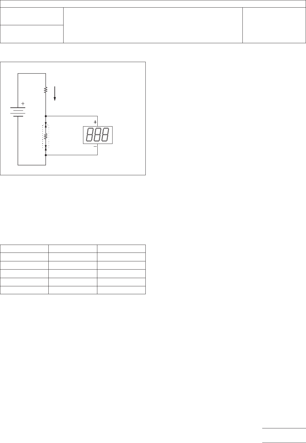
the resistance of the UUT rises to the upper limit of 5Ω, the
current will be 9.989 ma, just outside 0.1% on the low side.
This inaccuracy is well within the limits of the stanard.
T
able 1 Examples for Battery, Dropping
Resistor, and Accuracy
V
R Accuracy
6
600 -0.8%
9 900 -0.6%
12 1200 -0.4%
24 2400 -0.2%
48 4800 -0.1%
IPC-2.5.33.1-3
Figure
3 Simple Constant Current Source
UUT
0
TO 5
OHMS
10 MA
CURRENT
R
V
MILLIVOLT
METER
IPC-TM-650
Number
2.5.33.1
Subject
Measurement
of Electrical Overstress from Soldering Hand
Tools - Ground Measurements
Date
11/98
Revision
P
age3of3
电子技术应用 www.ChinaAET.com

1
Scope
This
test method deals only with transients gener-
ated within the Unit Under Test (UUT) and not with transients
originating elsewhere (i.e., power line transients), which propa-
gate through the UUT.
This procedure measures transient voltage events appearing
at the hot tip of an electric hand soldering/desoldering tool,
which could be seen by the workpiece. The test electrode and
measuring equipment represent a workpiece having a high
impedance.
There are two times when transients testing should be done:
• Equipment qualification for purchase
• Incoming inspection of new or repaired equipment
A storage oscilloscope is used to observe and measure tran-
sient events. The test electrode is coupled to the vertical input
of the oscilloscope via a 10 MΩ probe. The UUT may be iso-
lated from ambient electronic noise by placing it in a screen
room or shielded enclosure and supplying filtered AC power.
Inside the shield, the hot tip of the UUT is touched to the test
electrode.
This test may be falsely influenced by radio frequency interfer-
ence and electromagnetic interference from lighting and
equipment found in the workplace and testing area. This will
normally be demonstrated by ambient transients of 1.5 V peak
being present. At a minimum, shielded test leads should be
utilized. To avoid these influences it may be necessary to per-
form the leakage and transient tests in a screen room. In lieu
of a screen room a separate test procedure, see Method
2.5.33.4, which makes a low cost shielded enclosure, which
should provide adequate shielding for the performance of
these test procedures.
Warning:
This
is a laboratory test procedure that may of
necessity expose terminals that carry line voltages. All stan-
dard laboratory safety procedures regarding the setup and
performance of tests with line voltage equipment must be
observed at all times.
Caution:
This
test is performed with soldering systems at
their normal operating temperature. Test personnel must take
adequate precautionary steps to protect themselves and oth-
ers from potential burns.
2
Applicable Documents
ANSI/J-STD-001
Requirements
for Soldered Electrical and
Electronic Assemblies
IPC-TM-650 Test
Methods Manual
2.5.33 Measurement of Electrical Overstress from Solder-
ing Hand Tools
2.5.33.4 Measurement of Electrical Overstress from Solder-
ing Hand Tools - Shielded Enclosure
3
Test Specimens
Test
specimens for this procedure are
detailed in Method 2.5.33.
4
Equipment/Apparatus
Apparatuses
utilized by the pro-
cedures that make up this test method are given in 4.1
through 4.5.2.
4.1
Test
electrode (see Section 3)
4.2
Storage
oscilloscope, 100 Mhz bandwidth or faster, 1
MΩ input vertical amplifier
4.3
Power
line filter, 20 ampere @ 115 VAC, 50 dB insertion
loss @ 5 Mhz/50Ω
4.4
Oscilloscope
probe - X10 Attenuation
4.5
Optional
4.5.1
Screen
camera, diskette, or hard copy waveform
printer
4.5.2
Screen
room or shielded enclosure capable of accom-
modating the entire UUT, cord, and handpiece. A filtered AC
power receptacle shall be available from within (see Method
2.5.33.4).
4.6
Preparation of Apparatus
Turn
on the oscilloscope
and allow it to warm up.
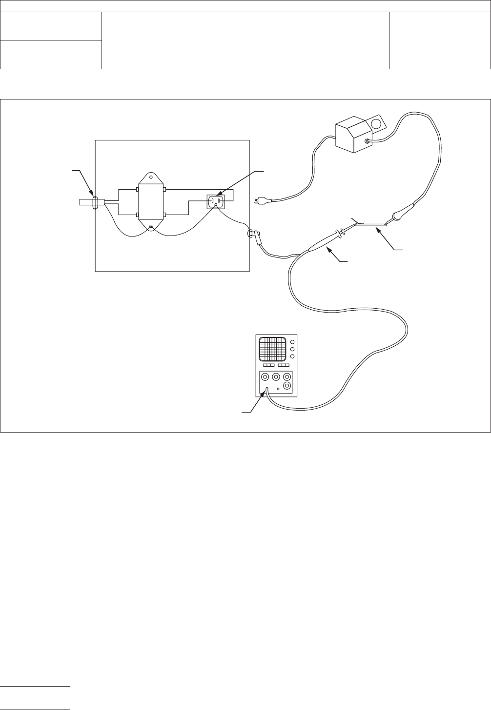
Connect the UUT to a shielded AC line filter assembly as
shown in Figure 1 and configure for typical operation.
Note: The
plugs are in power receptacles during measure-
ments. They are shown unplugged in Figure 1 for clarity.
The
Institute for Interconnecting and Packaging Electronic Circuits
2215 Sanders Road • Northbrook, IL 60062
IPC-TM-650
TEST
METHODS MANUAL
Number
2.5.33.2
Subject
Measurement
of Electrical Overstress from
Soldering Hand Tools - Transient Measurements
Date
11/98
Revision
Originating Task Group
Manual Soldering Task Group (5-22c)
Material
in this Test Methods Manual was voluntarily established by Technical Committees of the IPC. This material is advisory only
and its use or adaptation is entirely voluntary. IPC disclaims all liability of any kind as to the use, application, or adaptation of this
material. Users are also wholly responsible for protecting themselves against all claims or liabilities for patent infringement.
Equipment referenced is for the convenience of the user and does not imply endorsement by the IPC.
P
age1of4
电子技术应用 www.ChinaAET.com
Non-US
power receptacles may be different from those illus-
trated.
4.7
Calibration and Standardization
The
oscilloscope
(vertical and horizontal amplifiers) shall bear a current calibra-
tion sticker. The scope probe shall be adjusted/compensated
to display the square wave calibration signal generated by the
oscilloscope without undershoot or overshoot.
5
Procedure
5.1 Baseline Measurement
Turn
on the UUT and allow it
to warm up to a normal operating temperature. Touch the hot
tip to the tinned area of the test electrode. Apply solder to
form good electrical contact. Turn off the UUT. Adjust the
oscilloscope controls as required and record any ambient sig-
nals that are displayed by the oscilloscope. Attempt this for a
minimum of two minutes. Repeat this baseline test for a mini-
mum of three trials. If any ambient transients are greater than
1.5 V peak, measures must be taken to reduce the effects of
the ambient interference to below 1.5 V peak.
Place the UUT in a screen room or the shielded enclosure (see
Figure 2) if the test is to be conducted in a shielded enclosure.
If the shielded enclosure is utilized, arrange for support and/or
remote movement of the handpiece. Configure the UUT for
typical operation. In cases where function switches must be
operated, arrange for remote switch actuation, such as by
using a non-metallic rod through a small hole in the enclosure.
Position the tip of the handpiece for remote placement onto
the test electrode.
5.2
Test Measurement
Turn
on the UUT. Let the tip dwell
on the electrode while the UUT cycles power to maintain tem-
perature for a minimum of two minutes. Operate various other
functions of the UUT if present, such as the vacuum pump or
IPC-2.5.33.2-1
Figure
1 Apparatus for Transient Measurement
OSCILLOSCOPE
AC LINE
FIL
TER ASSEMBLY
1 MEGOHM
INPUT
RECEPTACLE
FOR UUT
UUT
10 MEGOHM
(X10) SCOPE
PROBE
TEST
ELECTRODE
STRAIN
RELIEF
TO
AC
AC
LINE
FILTER
METAL BOX
BLK BLK
WHTWHT
GRN GRN
GRN
IPC-TM-650
Number
2.5.33.2
Subject
Measurement
of Electrical Overstress from Soldering Hand
Tools - Transient Measurements
Date
11/98
Revision
P
age2of4
电子技术应用 www.ChinaAET.com