IPC-TM-650 EN 2022 试验方法.pdf - 第340页
1 Scope This test method is used to determine the adhe- sion quality of solder masks used on flexible circuits. 2 Applicable Documents IPC-A-42-G-KIT 1 Double-Sided Artwork 3 Test Specimen The IPC-A-42-G-KIT artwork pack…

5.1.2 For preproduction qualification, test specimens are to
be cleaned using cleaning methods as recommended by the
solder resist manufacturer and standard production methods
for comparison purposes prior to solder resist application.
5.1.3 Test specimens are to be coated and cured by the
standard production method.
5.1.4 Testing is to be conducted on specimens before and
after soldering in accordance with J-STD-003, Methods A, B,
C, or D with no accelerated aging.
5.2 Test
5.2.1
Press a strip of pressure sensitive tape, 50 mm
[1.97 in] minimum in length, firmly across the surface of the
test area removing all air entrapment. The time between appli-
cation and removal of tape shall be less than one minute.
Remove the tape by a rapid pull force applied approximately
perpendicular (right angle) to the test area. An unused strip of
tape must be used for each test.
5.3 Evaluation
5.3.1
Visually examine the tape and test area for evidence of
any portion of the material tested having been removed from
the specimen.
5.3.2 The report should note any evidence of material
removed by this test.
6 Notes
6.1
Figure 1 illustrates the coupon that is used for testing.
The black squares indicate metal. The white squares indicate
the base material. Solder mask is applied over the entire con-
ductor pattern.
6.2 If foreign material (oil, grease, etc.) is present on the test
surface the results may be affected.
6.3 Certification of 3M Brand 600 1/2 inch tape to CID-A-A-
113 is not required. The 3M Brand 600 1/2 inch tape is avail-
able through most office supply stores.
IPC-TM-650
Number
2.4.28.1
Subject
Solder Mask Adhesion - Tape Test Method
Date
03/07
Revision
F
Page2of2

1 Scope This test method is used to determine the adhe-
sion quality of solder masks used on flexible circuits.
2 Applicable Documents
IPC-A-42-G-KIT
1
Double-Sided Artwork
3 Test Specimen The IPC-A-42-G-KIT artwork package
provides the electronic Gerber information necessary for the
fabrication of the IPC B-42 test board. IPC-B-42 flexible test
patterns H1, H2, and/or H3, or production test samples with
solder mask coating. Each flexible section shall be separated
and tested independently.
4 Apparatus 3.18 ± 0.1 mm [0.125 ± 0.004 in] diameter
mandrel (metal rod).
5 Procedures
5.1 Test
5.1.1
Bend the test specimen around the mandrel so that
the ends of the test specimens are on the same side of the
mandrel and nominally parallel to each other. (The test speci-
men forms a ‘‘U’’ shape around the mandrel.) Each cycle
must be at the same point on the flexible circuit.
5.1.2 Flip the test specimen so that its opposite surface is
against the metal rod and repeat 5.1.1.
5.1.3 Repeat 5.1.1 and 5.1.2 nine times (ten cycles total) for
each of the test specimens.
5.2 Evaluation Visually examine the flexible circuit test pat-
tern with corrected 20/20 vision without magnification for sol-
der mask delamination or cracks.
1. www.ipc.org/onlinestore
3000 Lakeside Drive, Suite 309S
Bannockburn, IL 60015-1249
IPC-TM-650
TEST METHODS MANUAL
Number
2.4.29
Subject
Solder Mask - Adhesion to Flexible Circuits
Date
03/07
Revision
C
Originating Task Group
Solder Mask Performance Task Group (5-33b)
Material in this Test Methods Manual was voluntarily established by Technical Committees of IPC. This material is advisory only
and its use or adaptation is entirely voluntary. IPC disclaims all liability of any kind as to the use, application, or adaptation of this
material. Users are also wholly responsible for protecting themselves against all claims or liabilities for patent infringement.
Equipment referenced is for the convenience of the user and does not imply endorsement by IPC.
Page1of1
ASSOCIATION CONNECTING
ELECTRONICS INDUSTRIES
®
1
Scope
This
test method is to determine the impact resis-
tance of polymer film circuitry when exposed to a series of
falling ball impingements. The method is used to evaluate the
resistance to chipping, flaking, convolution or other forms of
separation of the polymer film from either the conductor or
base laminate material surfaces.
2
Applicable documents
None
3
Test specimen
IPC-B-25
Multi-Purpose Test Board
4
Equipment/Apparatus
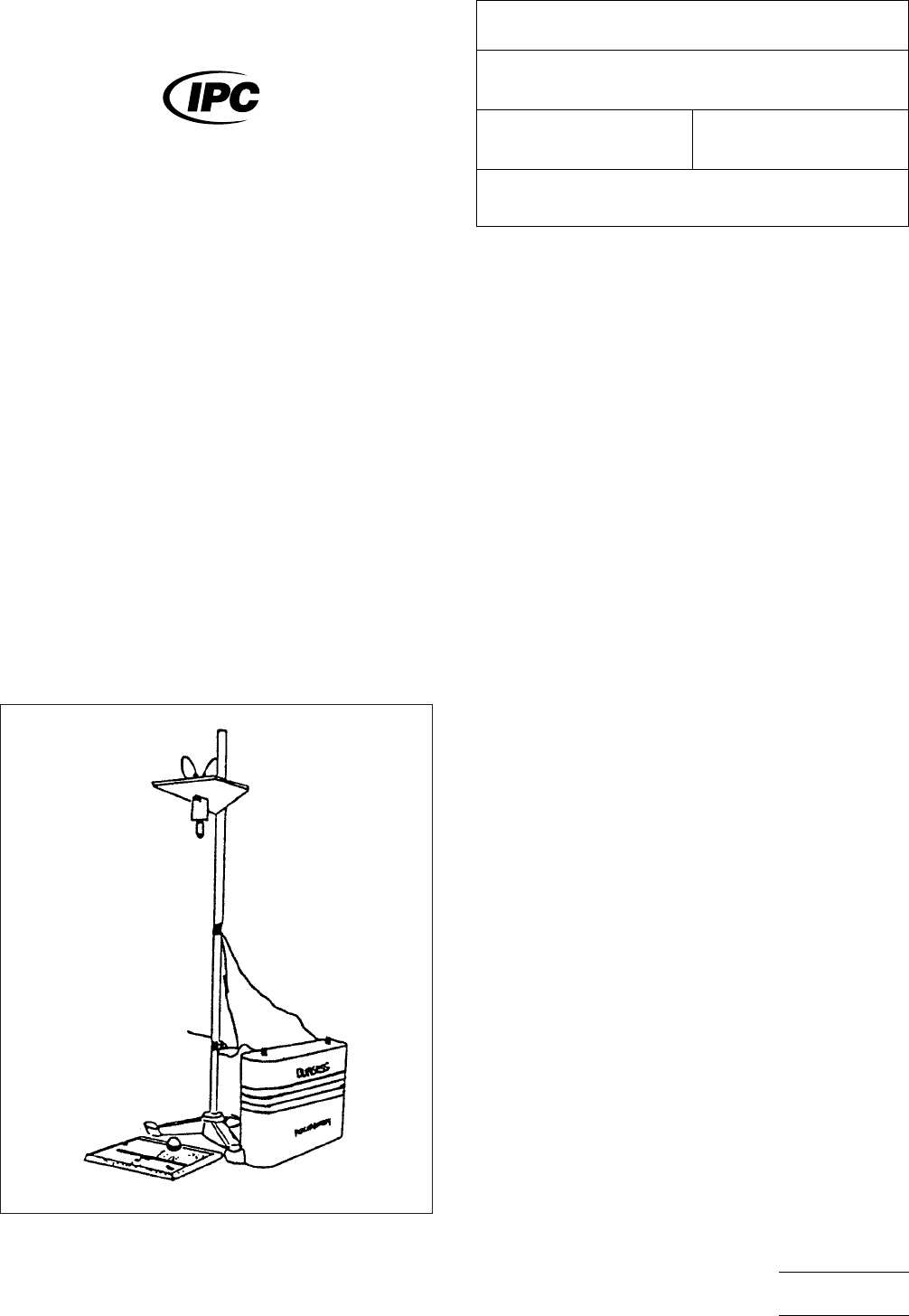
4.1
A
suitable electromagnetic apparatus to precisely con-
trol the height and the point of impact of the falling ball (see
Figure 1)
4.2
The
test ball shall be 25 mm diameter, 67 gram preci-
sion steel ball.
4.3
When
testing flexible circuits, the test specimen shall be
placed on a hard smooth surface. Use of at least 0.6 cm cold
rolled steel sheet stock.
5
Procedure
5.1 Preparation
5.1.1
Adjust
the fall height by setting the solenoid core at 53
cm ± 0.3 cm from the top surface of the test specimen.
5.2
Test
5.2.1
Place
the steel ball on the underside of the solenoid
core with the solenoid energized.
5.2.2
Place
the test specimen below the falling ball in such
a manner as to strike the center of feature (L) on test speci-
men IPC-B-25.
5.2.3
Release
the falling ball by de-energizing the solenoid
magnet.
5.2.4
It
is necessary to catch the ball immediately after
impact so as not to permit more than one blow at a time.
5.2.5
Repeat
this procedure for 10 cycles and observe the
test specimen after each blow.
5.2.6
Perform
the same test (also for l0 cycles)on any area
of the test specimen having no circuitry.
5.2.7
Repeat
the same test in such a manner as to strike
the edge of the feature (L) 10 times.
5.3
Evaluation
Visually
examine the test specimen for
chipping, flaking, convolution, or other forms of separation of
the polymer film.
6 Notes
6.1 The
test apparatus shown in Figure 1 can easily be
assembled using a standard laboratory stand and clamps, a
12 volt DC Solenoid, and a 12 Volt battery.
IPC-2-4-30-1
Figure
1 Falling Ball Impact Test Apparatus
The
Institute for Interconnecting and Packaging Electronic Circuits
2215 Sanders Road • Northbrook, IL 60062-6135
IPC-TM-650
TEST
METHODS MANUAL
Number
2.4.30
Subject
Impact
Resistance, Polymer Film
Date
10/86
Revision
Originating Task Group
N/A
Material
in this Test Methods Manual was voluntarily established by Technical Committees of the IPC. This material is advisory only
and its use or adaptation is entirely voluntary. IPC disclaims all liability of any kind as to the use, application, or adaptation of this
material. Users are also wholly responsible for protecting themselves against all claims or liabilities for patent infringement.
Equipment referenced is for the convenience of the user and does not imply endorsement by the IPC.
P
age1of1
电子技术应用 www.ChinaAET.com