IPC-TM-650 EN 2022 试验方法.pdf - 第607页
4.6 Coaxial Cable Impedance: 50 - 2 Ω RG-58A, RG-58C, or equivalent; Termination: GR874 connectors, both ends; Length: approximately 61 cm 4.7 Load General Radio type GR874 or equivalent 50 Ω load. This is an optional it…
4.1
In
this test, characteristic impedance is measured by
TDR. Commercial TDRs are readily available and consist of
pulse generator and sampling oscilloscopes. Rise times of the
pulses are usually less than 250 picoseconds (250 x 10-12
sec.), which gives a resolution sufficient to detect discontinui-
ties smaller than 2.5 cm in length. Since the pulse rise times
generally used now in electronic equipment are not this fast, a
TDR is adequate for testing. Also required for this test is a lab
standard air line to establish a reference impedance (Z
0
ref.)
and
a standard cable connection device at the air line output
(see Figure 1).
4.2
A
TDR, such as a Hewlett-Packard 1415A, Hewlett-
Packard 1815A, Tektronix 1 S2, or equivalent
4.3
The
standard air line used should be a General radio
874-L20 (20 cm), 874-L30 (30 cm), or equivalent for Z
0
=
50Ω.
4.4
Cable Holders
Fixture
of plexiglass or other nonmetal-
lic material. Cable hangers to suspend the cable in air. Refer
to Figure 3.
4.5
The
standard cable connection device used should
match Figure 4. It is made from a General radio cable connec-
tor type 874-C62A.
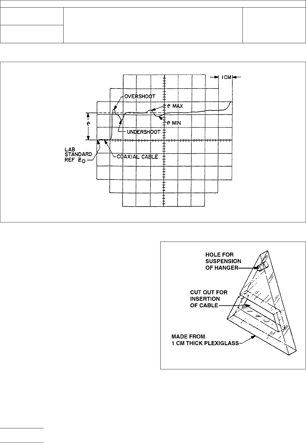
IPC-2-5-18-5
Figure
2 TDR Trace for a Typical Cable
IPC-2-5-19-1-4
Figure
3 Sample Cable Hanger
IPC-TM-650
Number
2.5.18
Subject
Characteristic
Impedance Flat Cables (Unbalanced)
Date
7/84
Revision
B
P
age2of4
电子技术应用 www.ChinaAET.com
4.6
Coaxial Cable
Impedance:
50 - 2Ω RG-58A, RG-58C,
or equivalent; Termination: GR874 connectors, both ends;
Length: approximately 61 cm
4.7
Load
General
Radio type GR874 or equivalent 50Ω
load. This is an optional item, which is used to calibrate the
TDR.
5
Procedure
5.1
Allow
a minimum of one hour for TDR warm-up and
calibrate the instrument per manufacturer’s instructions.
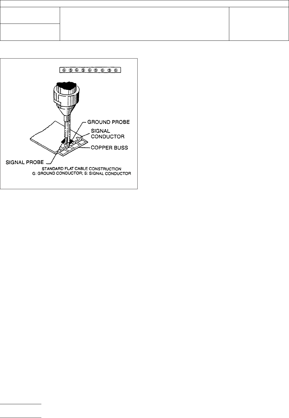
5.2
Prepare
the test specimen by stripping approximately 13
mm of insulation from one end of cable. Separate the ground
and signal conductors and solder a copper buss across the
grounds (see Figure 5).
5.3
Adjust
the TDR settings as follows:
Vertical: 0.1 e/cm
Distance/time: 20 ns/cm.
Magnifier: 50 x (For equipment other than Hewlett-Packard,
use settings as close as possible to these.)
Insert the 30 cm air line into the output of the TDR. This will
serve as the 50Ω reference. Attach the coaxial cable to the air
line and terminate with the impedance probe. Vertically center
the 50Ω reference line on the TDR graticule.
5.4
Press
the probe against the conductor to be tested
insuring the ground of the probe is against the cable ground
(see Figure 5) and check the vertical placement of the 50Ω
reference; re-center if necessary.
5.5
Adjust
the distance/time magnifier to 5 or 10 and rotate
the magnifier delay dial until the total length of the cable is vis-
ible on the screen. Measure the vertical reflection coefficient
(e) in cm as illustrated in Figure 2.
5.7
Calculate
the characteristic impedance (Z
0
)
as follows:
Z
0
= 50
(
1 + e
1 − e
)
(Ω)
Calculate
Z
0
of
the cable measuring as shown in Figure 2.
Calculate Z
0
max., e = e max;
Z
0
min., e = e min.
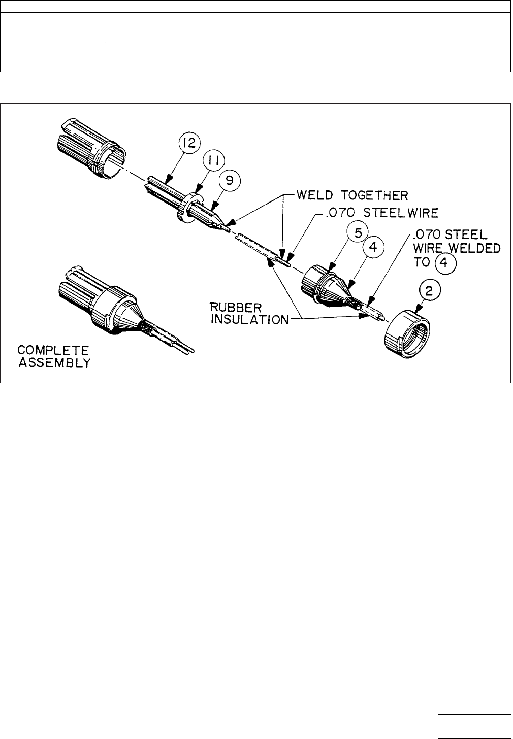
IPC-2-5-18-3
Figure
4 Cable Connection Device. Refer circled items to parts list. Made from General Radio Co. Type 874-C62A.
IPC-TM-650
Number
2.5.18
Subject
Characteristic
Impedance Flat Cables (Unbalanced)
Date
7/84
Revision
B
P
age3of4
电子技术应用 www.ChinaAET.com
6 Notes
6.1
The
TDR employs a pulse rise time less than 250 pico-
seconds. A pulse of this rise time is extremely rich in harmon-
ics extending well into the GHz region of the frequency spec-
trum. The impedance probe illustrated in Figure 1 is designed
to minimize the effects of impedance mismatch at the con-
nection; therefore, it is suggested that a probe of this type be
used for the impedance measurement. The importance of a
good connection between the cable under test and the TDR
can not be overemphasized.
Cables longer than3minlength may be tested, but care
must be exercised so as not to confuse the effect of increased
wire resistance with an apparent increase in impedance as the
magnifier delay dial is rotated to observe the longer cable
length (function of attenuation, which includes wire size).
6.2
Under
no circumstances should the cable be tested
while in a coiled form due to the effect of increased induc-
tance.
6.3
Keep
cable a minimum of 15 cm away from any dielec-
tric or ground plane including metal, wood, etc. (except in
step 5.5).
6.4
Measurement
of Z
0
of
unknown cable length should be
made as close as possible to the cable connection device
(after overshoot and undershoot).
6.5
The
reference Z
0
cable
may be positioned after the
RG58C cable and before the cable connection device. There-
fore, the reference Z
0
is
adjacent to the test cable on the TDR
trace.
IPC-2-5-18-4
Figure
5 Connection of Impedance Probe to Sample
under Test
IPC-TM-650
Number
2.5.18
Subject
Characteristic
Impedance Flat Cables (Unbalanced)
Date
7/84
Revision
B
P
age4of4
电子技术应用 www.ChinaAET.com