IPC-TM-650 EN 2022 试验方法.pdf - 第238页
5.3.2 Fatigue Test The number of cycles to failure is the flexural fatigue life in fully reversed bending for the bend radius corresponding to the radius (1/2 diameter) of the test mandrel used. An average flexural life …
batch
or lot basis, and this fractional value of t
M
/t
is then mul-
tiplied by all other micrometer, t, values to achieve core values
for all samples.
5.1.4
Connect
all conductors to be tested and monitored in
series and attach thin relay leads to the two free ends.
5.1.5
Attach
test specimen to the ends of two sample hold-
ers with adhesive tape and clamp 224 grams circuit weight
to the free ends of the sample holders to form a loop (see Fig-
ure 1).
Note: For flexural fatigue test lasting in excess of 1000 cycles,
the adhesive tape attachment needs to be substantial enough
to prevent relative sliding of the specimen and sample holder
as a result of cyclic flexure movements.
5.2
Test Procedure
5.2.1
Mount
mandrels to flex tester and adjust the support
roller positions for a clearance of 1.27 mm (shim provided)
between rollers and mandrels.
Note: For the ductility test, it is important that the specimens
fail between 30 cycles and 500 cycles. Suggested mandrel
diameters are 19.05 mm for double-sided laminate and 6.35
mm for single-sided laminate, but for some samples, mandrel
diameters different from the above suggested may be neces-
sary. Larger mandrel diameters result in longer cyclic life and
smaller diameters in shorter life.
5.2.2
Mount
the test specimen between mandrels, plug the
relay leads into the relay jacks, set the counter to zero, and
start the flex tester.
5.2.3
Electrical
discontinuity constitutes failure; the flex
tester stops automatically.
5.2.4
Record
cycles-to-failure indicated on counter.
5.3
Evaluation
5.3.1 Ductility Test
5.3.1.1
Calculate
the ductility for each specimen by itera-
tively solving the formula below:
N
f
−0.6
D
f
0.75
+ 0.9
S
u
E
[
exp(D
f
)
0.36
]
(0.1785
log
10
5
N
f
)
−
2t
M
2
e
+ t
= 0
where:
D
f
=
fatigue ductility, inch/inch (x100,%)
N
f
=
cycles-to-failure
S
u
=
ultimate tensile strength, psi
E = modulus of elasticity, psi
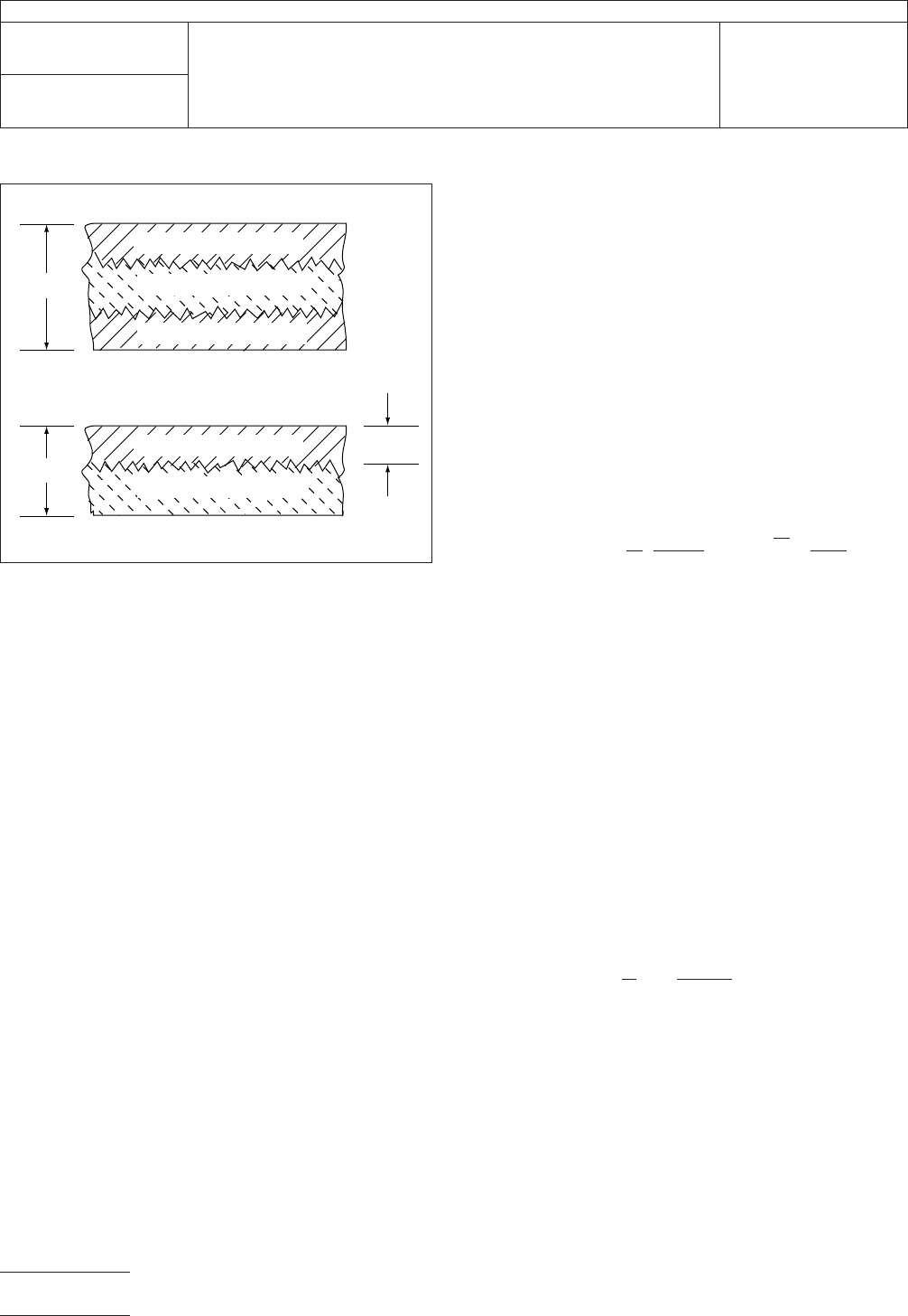
t
M
=
core thickness, inch
t = specimen micrometer thickness, inch
ρ = mandrel radius of curvature, within 0.005 mm
Note: This formula is exact only for symmetric cross sections.
In the case of non-symmetrical single-sided laminate, the
uncertainty of the location of the neutral axis introduces some
error. The error in D
f
is
kept below 20% if
[
t
t
M
−1
]
2
E
substrate
E
≤0.1
IPC-D-330
gives more detailed information for the accurate
determination of the location of the neutral axis and the cyclic
strains.
Note: Determine S
u
as
per IPC-TM-650, Method 2.4.18.
Determine E during the test for S
u
by
unloading and reloading
after about 2% elongation and measuring the slope of the
reloading curve.
5.3.1.2
Report
the average product ductility from at least
three specimens.
IPC-2432-1
Figure
2 Core Thickness
t
M
t
t = t
M
SUBSTRA
TE
CONDUCTOR
CONDUCTOR
SUBSTRATE
CONDUCTOR
IPC-TM-650
Number
2.4.3.2
Subject
Flexural
Fatigue and Ductility, Flexible Metal-Clad Dielectrics
Date
3/91
Revision
C
P
age2of3
电子技术应用 www.ChinaAET.com

5.3.2
Fatigue Test
The
number of cycles to failure is the
flexural fatigue life in fully reversed bending for the bend radius
corresponding to the radius (1/2 diameter) of the test mandrel
used. An average flexural life from at least three specimens
should be reported.
5.3.3
Fatigue Behavior
The fatigue behavior of a sample
can be obtained by determining the flexural fatigue life with a
number of different diameter mandrels. Plotting the results in
a strain range versus fatigue life Manon-Coffin plot log ∆ε =
[2t
M
/(2tρ +
t)] versus log N allows intrapolation and extrapola-
tion to other bend radii or fatigue lives.
6 Notes
For
further technical details, reference the material
given in 6.1 through 6.3.
6.1
IPC-TP-204
Engelmaier,
W., A New Ductility and Flex-
ural Fatigue Test Method for Copper Foil and Flexible Printed
Wiring, April, 1978
6.2
Engelmaier,
W., Fatigue Ductility for Foils and Flexible
Printed Wiring, Program No. 1883D HP-67/97 User’s Library,
Hewlett Packard Co., Corvallis, Oregon, 1978.
6.3
Engelmaier,
W., Fatigue Ductility Flex Tester, Drawing
L520163, Bell Telephone Laboratories, Inc., Whippany, New
Jersey, 1978.
6.4
Test Equipment Sources
The
equipment sources
given in 6.4.1 and 6.4.2 represent those currently known to
the industry. Users of this test method are urged to submit
additional source names as they become available, so this list
can be kept as current as possible.
6.4.1
Fatigue
Ductility Flex Tester, Universal Mfg. Co., Inc.,
(201) 374-9800, 1168 Grove St., Irvington, NJ 07111.
6.4.2
JDC
Precision Sample Cutter, Model JDC 125-N or
equivalent.
IPC-TM-650
Number
2.4.3.2
Subject
Flexural
Fatigue and Ductility, Flexible Metal-Clad Dielectrics
Date
3/91
Revision
C
P
age3of3
电子技术应用 www.ChinaAET.com
1.0
Scope
This
test is designed to determine the flexural
strength of laminates of thicknesses greater than, or equal to,
0.51 mm [0.020 in] by applying a specific load to a specific
size and shaped specimen.
2.0
Applicable Documents
ASTM-D-790
Flexural
Properties for Unreinforced and Rein-
forced Plastics and Insulating Material.
IPC-TM-650
Methods
2.3.6, Etching Ammonium Persulfate
Method 2.3.7, Etching Ferric Chloride
Method 2.3.7.1, Cupric Chloride Etching
3.0
Test Specimens
3.1 Size and Configuration
Dimensions
of the specimens
shall be as shown in Table 1. Edges of the specimens shall be
free of fractures, delamination, or roughness by means of
sanding or equivalent means (do not radius the edges.)
3.2
Quantity and Sampling
Unless
otherwise specified,
four specimens shall be tested, two in the lengthwise and two
in the crosswise direction of the sample sheet or panel.
4.0
Apparatus or Material
4.1 Tester
A
standard tension and compression test appa-
ratus which can be operated at a constant rate of crosshead
movement shown in Table 1. The error in the load measuring
system shall not exceed ± 1%. The loading nose and supports
shall have cylindrical surfaces. The radius of nose and sup-
ports shall be in accordance with ASTM-D-790 (in order to
avoid excessive indentation).
4.2
Etching
system capable of complete removal of the
metallic cladding.
4.3
Measuring
devices capable of determining specimen
widths to the nearest 0.025 mm [0.001 in] and specimen
thickness to the nearest 0.0025 mm [0.0001 in].
5.0
Procedure
5.1 Specimen Preparation
5.1.1
When
applicable, chemically etch off all metallic clad-
ding in accordance with standard industry etching practices.
For referee purposes, etching shall be in accordance with
2.3.6, 2.3.7, or 2.3.7.1.
5.1.2
Cut
specimens to the size as shown in Table 1 and
smooth the edges of specimens. Measure and record speci-
men width to the nearest 0.025 mm [0.001 in] and thickness
to the nearest 0.0025 mm [0.0001 in].
5.2
Measurement
5.2.1
Set
tester for the required span and crosshead verti-
cal speed as specified in Table 1.
5.2.2
Align
the loading nose and supports so that the axis of
the cylindrical surfaces are parallel and the loading nose is
midway between the supports.
T
able 1
Specimen
Dimensions Test Parameters
Nominal thickness
1
mm
[inches]
Width
2
mm
[inches]
Length
3
mm
[inches]
Span
mm [inches]
Speed of testing
mm [inches] per min.
0.79
[0.031] 25.4 [1.0] 63.5 [2.5] 15.9 [0.625] 0.51 [0.020]
1.57 [0.062] 25.4 [1.0] 76.2 [3.0] 25.4 [1.0] 0.76 [0.030]
2.36 [0.093] 25.4 [1.0] 88.9 [3.5] 38.1 [1.5] 1.02 [0.040]
3.18 [0.125] 25.4 [1.0] 101.6 [4.0] 50.8 [2.0] 1.27 [0.050]
6.35 [0.250] 12.7 [0.5] 152.4 [6.0] 101.6 [4.0] 2.03 [0.080]
1.) Nominal thicknesses other than those listed shall be prepared and tested in accordance with the next greater nominal thickness.
2.) Width as cut and smoothed to within 5% of nominal shown.
3.) Length as cut (not necessary to smooth) to within 10% of nominal shown.
The
Institute for Interconnecting and Packaging Electronic Circuits
2215 Sanders Road • Northbrook, IL 60062-6135
IPC-TM-650
TEST
METHODS MANUAL
Number
2.4.4
Subject
Flexural
Strength of Laminates (at Ambient
Temperature)
Date
12/94
Revision
B
Originating Task Group
MIL-P-13949 Test Methods Task Group (7-11b)
Material
in this Test Methods Manual was voluntarily established by Technical Committees of the IPC. This material is advisory only
and its use or adaptation is entirely voluntary. IPC disclaims all liability of any kind as to the use, application, or adaptation of this
material. Users are also wholly responsible for protecting themselves against all claims or liabilities for patent infringement.
Equipment referenced is for the convenience of the user and does not imply endorsement by the IPC.
P
age1of2
电子技术应用 www.ChinaAET.com