IPC-TM-650 EN 2022 试验方法.pdf - 第371页
5.3.5 Place the gage/terminal assemblies in their original position over the reference lines, using only enough pressure to allow the assemblies to be tacked down. Overlay the gage/ terminal area with thin pieces of PTFE…

4.26
Thermal
cycling chamber for thermal cycling with a
heat rise capability of 2 °C to 30 °C/min [3 °F to 54 °F/min],
and equipped with a programmable temperature control sys-
tem
4.27
Thermocouple
Type J (Type may be used where appli-
cable)
4.28
Titanium
Silicate Standard
Corning Glass Works Code 7971ULE, or
Measurements Group Inc. #TSB-1
4.29
Wheatstone
Bridge
*See 6.1 for source of materials.
5
Strain Gage Mounting Procedure
The
procedure for
mounting the strain gages to the PCB material and titanium
silicate or other standards as appropriate, includes the prepa-
ration of the adhesive and specimen bonding surfaces, appli-
cation of the adhesive, attachment of the strain gages, and
the assembly of the Alloy 42 holding fixture. (The Alloy 42 fix-
ture may not be required, depending on specimen type and
application.)
5.1
Adhesive Preparation
The
strain gages are to be
mounted using adhesive M-Bond 610 or equivalent. The
M-bond 610 is a two-component system that is mixed as fol-
lows:
5.1.1
The resin and curing agent bottle are to be at room
temperature before opening.
5.1.2
Using
the disposable plastic funnel, empty contents of
bottle labeled ‘Curing Agent’ into the bottle of resin labeled
‘Adhesive’ (discard funnel).
5.1.3
After
tightening the brush cap (included separately),
thoroughly mix contents of the ‘Adhesive’ bottle by shaking
for 10 seconds.
5.1.4
Identify
the ‘Adhesive’ bottle by writing the date on the
label. Allow the freshly mixed adhesive to stand for a minimum
of one hour before using.
5.2
Sample Preparation
Two
strain gages are applied to
one side of the PCB board test specimen at right angles to
one another and to the titanium silicate reference standard
using the following procedure:
5.2.1
Mark
reference lines perpendicular to each other on
the test specimen and the titanium silicate standard. For most
printed board material this is easily accomplished by making a
burnish mark with the wooden end of a cotton-tipped swab
applicator.
5.2.2
Thoroughly
degrease the gaging areas with cleaning
solution.
5.2.3
Dry
abrade the area to be bonded with 220 or 320 grit
silicon carbide paper, and follow with a final with a final abrad-
ing with 320 or 400 grit paper on the areas thoroughly wetted
with M-prep Conditioner A. Scrub the gaging areas with
repeated applications of Conditioner A using a cotton tipped
swab and until a clean cotton swab or lint free pad is no
longer discolored. Remove all residues and Conditioner A by
wiping thoroughly with a gauze sponge. Do not allow to dry
while cleaning before use of the sponge to prevent the con-
taminating films.
5.2.4
Apply
a liberal amount of M-Prep Neutralizer 5 and
scrub with a cotton-tipped applicator or lint free pad. Using a
single slow wiping motion with gauze sponge, carefully dry the
surface. Do not wipe with a back and forth motion as this may
allow contaminants to be redeposited.
5.3
Strain Gage Installation
Apply
the strain gages to the
previously cleaned areas of the PCB specimen and the tita-
nium silicate standard using the following procedure:
5.3.1
Remove
the gage from the acetate envelope with
tweezers; do not bend the gages. Place the gage bond side
down onto the cleaned area of the specimen. If a solder ter-
minal is to be incorporated, position it next to the gage. Place
a short length of Mylar tape over about half of the gage tabs
and entirely over the terminals.
5.3.2
Peel
back one end of the taped assembly (by lifting at
a small angle) so as to raise both gage and terminal. By curl-
ing the Mylar tape back upon itself, it will remain in position to
be accurately relaid following the application of the adhesive.
5.3.3
Apply
the M-Bond 610 adhesive with a cap brush over
the gage surface to form a thin uniform coating. Repeat the
application technique to the specimen gage area. Do not
allow adhesive to come in contact with the tape adhesive.
5.3.4
Air
dry the assemblies for 30 to 40 minutes at 24 °C ±
2 °C [75 °F ± 4 °F] and 40 to 55% relative humidity.
IPC-TM-650
Number
2.4.41.2
Subject
Coefficient
of Thermal Expansion—Strain Gage Method
Date
05/04
Revision
A
P
age2of4
电子技术应用 www.ChinaAET.com
5.3.5
Place
the gage/terminal assemblies in their original
position over the reference lines, using only enough pressure
to allow the assemblies to be tacked down. Overlay the gage/
terminal area with thin pieces of PTFE tape, and anchor them
in position with pieces of Mylar tape across the ends.
5.3.6
Cut
the silicone gum pads to size slightly larger than
the gage/terminal areas, carefully centering them in position.
Larger pads may restrict proper spreading of the adhesive
and entrap residual solvents during the curing process.
5.3.7
Use
spring clamps or dead weights to apply pressure
(275 to 350 kN/m
2
[40
to 50 psi]) and place in the curing oven
which is to be at room temperature.
5.3.8
Raise
the temperature to 100 °C ± 3 °C [212 °F ±
6 °F] (use 79 °C [174 °F] if using M-Bond 600) at a rate of
3 °C to 11 °C/min [5 °F to 20 °F/min], and cure for 4 1/2 to 5
hours. Air bubble entrapped in the adhesive, uneven glue
lines, and high adhesive stresses often result from starting
with a hot oven.
5.3.9
Remove
the specimens after allowing the oven to cool
below 55 °C [131 °F], remove clamps and Mylar tape, and
clean the entire surface with isopropyl alcohol to remove
residual tape adhesive. Wipe dry with a gauze sponge.
5.3.10
Post
cure for 2 to 2 1/2 hours at 40 °C [104 °F]
(30 °C [86 °F] per M-Bond instructions) above the test upper
limit temperature. Care must be taken, if base materials hav-
ing low T
g
values
(FR-4) are to be tested.
5.3.11
Bond
the solder tabs 6.4 mm [0.25 in] from the strain
gages. The gage leads are to looped slightly prior to soldering
to prevent inducement of strain resistance changes. Solder
tabs may be attached in the same step as the strain gages.
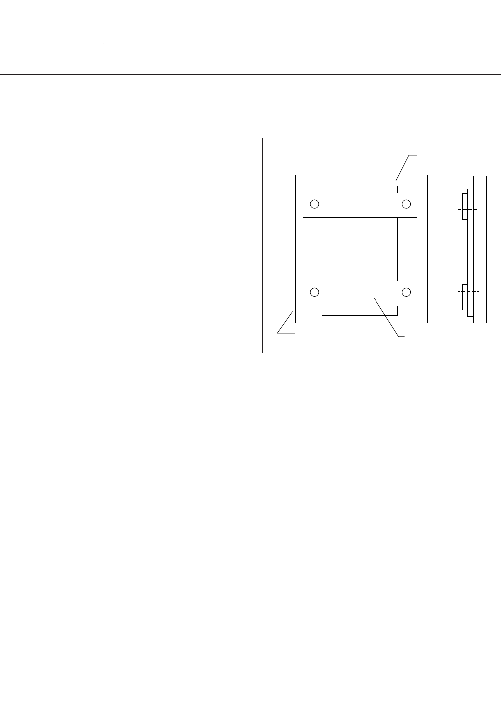
5.4
Specimen Fixture Preparation
(If
required, Figure 1)
5.4.1
The
PCB and titanium silicate standards, once
assembled with the strain gages, are fixtured to prevent bend-
ing or warping by the straps labeled PL in Figure 1 during the
temperature cycle test. The fixture used for the specimens will
not interfere with the thermal expansion of the specimens
being tested.
The fixture is constructed of 1.25 mm [0.050 in] thick Alloy 42
plated with 0.025 mm [0.001 in] of copper. This material was
chosen because of its thermal expansion properties that are
close to that of the test specimens. Plated Alloy 42 straps are
used to gently hold the specimen flat to the fixture. Other
materials that may closely match the CTE of the test speci-
men may be used.
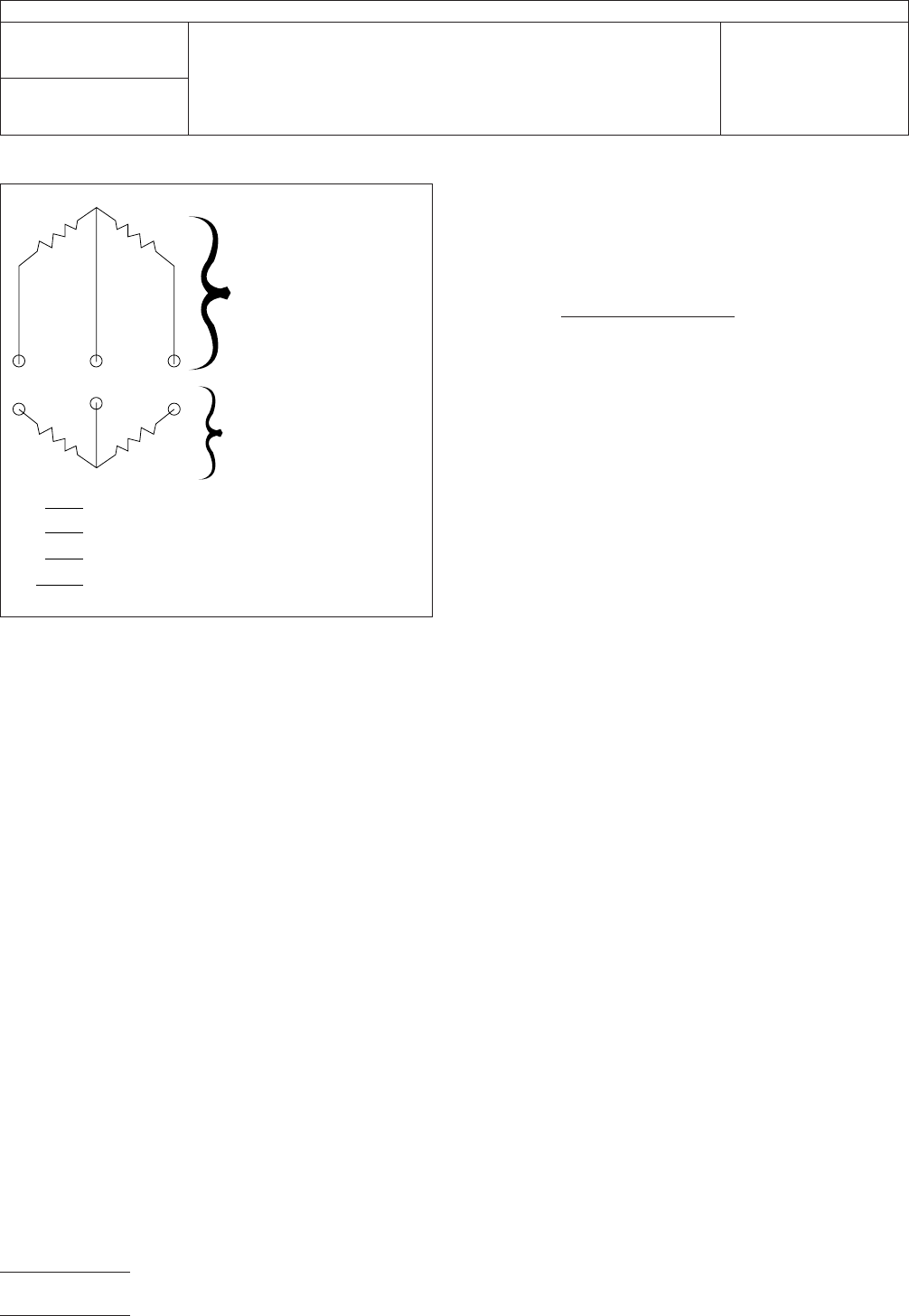
5.5
Test Configuration
Connect
two strain gages, one to
the test specimen and one to the to the titanium silicate stan-
dard, in adjacent arms forming a half bridge; the remaining
half of the Wheatstone bridge being completed with the
Wheatstone bridge instrument (see Figure 2). Repeat for the
remaining two strain gages, one on the test specimen and
one on the titanium silicate standard with a second Wheat-
stone bridge instrument in the circuit.
Attach (tape) thermocouple to the sample within a 6.0 mm
[0.25 in] of the measurement area.
5.6
Specimen Conditioning/Thermal Cycling
Clean
the
specimens by immersing in M-Line solvent with agitation for
15-20 seconds. Allow to dry for 1 to 1 1/2 hours at 40 °C ±
5 °C [105 °F ± 9 °F].
5.6.1
Place
the specimens and the reference standards in
the thermal cycling chamber (with programmable temperature
control) set at 20 °C [68 °F] and allow to stabilize for 30 to 40
minutes or as required to relieve strain gage attachment
stresses.
5.6.2 Increase
temperature at a rate of 2 °C/min [3 °F/min]
up to 130 °C [266 °F] or other test temperature designated,
allowing the specimens to stabilize for 10 minutes or longer, if
IPC-24412-1
Figure
1 Test Fixture Configuration
Sample
Strap 2PL
Base Plate
▼
▼
▼
IPC-TM-650
Number
2.4.41.2
Subject
Coefficient
of Thermal Expansion—Strain Gage Method
Date
05/04
Revision
A
P
age3of4
电子技术应用 www.ChinaAET.com
required.
Decrease the temperature to –55 °C ± 2 °C [–67 °F
± 3 °F] or other temperature designated and allow to stabilize
for 10 minutes or until no further changes are noted on the
meter. Increase the temperatures to 25 °C [77 °F] at the same
rate and allow the specimens to stabilize.
5.6.3
Throughout
the thermal cycle, the temperature and
change in resistance as noted on the meter(strain) should be
recorded at the desired time and temperature (two minute
intervals).
5.7
Calculation of CTE
Plot
the gage resistance versus
the temperature. Measure the slope of the line between the
temperatures of interest and record.
The equation for calculating the Coefficient of Thermal Expan-
sion, ∝, are:
∝ = ∆R/R(GF)∆T
Where ∝ = the coefficient of thermal expansion R = gage
resistance reading
∆R = the change in resistance reading
∆T = the change in temperature
GF = the Gage Factor of a particular gage and gage con-
figuration and is furnished by the strain gagemanufacturer.
The GF for the WK gage is near 2.1
Example:
Resistance reading at 20 °C [68 °F] = 352.39
Resistance reading at 170 °C [338 °F] = 353.40
GF as furnished by manufacturer = 2.11
∝ =
(353.40 – 352.39)
(353.40
X 2.11 X 150)
= 9.03 ppm/°C
Note:
The
graph plot of ∆R/∆T will allow selection of any tem-
perature point.
All strain and temperature data should be recorded on a disk.
Software packages are available that the raw data (resistance
changes and temperature) to strain and temperature. The
software compensates for gage factor with temperature,
apparent strain of the gage, and the bridge configuration in
reducing the data. The software also uses the data from the
titanium silicate standard to adjust the reduced data of the
test specimen.
6 Notes
6.1
Suggested Sources of Materials
6.1.1
Source
of Adhesive System
Micro-Measurements Division
Measurements Group Inc.
P. O. Box 27777
Raleigh, NC 27611
Phone: (919) 365-3800
6.1.2 Information Bulletin
Micro-Measurements Division
Measurement Group Inc.
P.O. Box 27777
Raleigh, NC 27611
Phone (919) 365-3800
Bulletin # B130-10
6.1.3
Titanium
Silicate Standard
Corning Glass works
Corning, NY 14831
Micro-Measurements Division
Measurement Group Inc.
P.O. Box 27777
Raleigh, NC 27611
Phone (919) 365-3800
IPC-24412-2
Figure
2 Wheatstone Bridge Instrumentation Hookup
R Gage on Unknown
R Gage on Standard
R Standard Resistors on Instrument
M Direct Reading Strain Meter
External or Measurement
Half Bridge
Internal or Instrument
Half Bridge
U
S
K
R
U
R
S
R
K
R
K
M
IPC-TM-650
Number
2.4.41.2
Subject
Coefficient
of Thermal Expansion—Strain Gage Method
Date
05/04
Revision
A
P
age4of4
电子技术应用 www.ChinaAET.com