IPC-TM-650 EN 2022 试验方法.pdf - 第620页
1 Scope This method is used to determine the attenuation of balanced and unbalanced cables. 2 Applicable Documents None 3 Test Specimen 3.1 30.5 meters of completed flat cable 4 Apparatus 4.1 H.R. Model #8568A or equival…

5.2.5
After
allowing the meter to ‘‘charge’’ for 60 seconds,
switch to ‘‘measure’’ and read the meter in megohms after
the indicator settles down (usually within 60 seconds).
5.3
Evaluation
Readings
shall be recorded to two signifi-
cant digits in megohms.
6 Notes
6.1
This
method can be used in substitution for surface
resistance. Volume resistivity cannot be replaced by this
method, but other tests such as dielectric strength, dissipa-
tion factor, and dielectric constant will give a better indication
of the electrical properties than volume resistivity.
IPC-TM-650
Number
2.5.27
Subject
Surface
Insulation Resistance of Raw Printed Wiring Board
Material
Date
3/79
Revision
P
age2of2
电子技术应用 www.ChinaAET.com

1
Scope
This
method is used to determine the attenuation
of balanced and unbalanced cables.
2
Applicable Documents
None
3
Test Specimen
3.1
30.5
meters of completed flat cable
4
Apparatus
4.1
H.R.
Model #8568A or equivalent spectrum analyzer
4.2
H.R.
Model #8444A or equivalent 2 tracking generator
4.3
Two
RG-223/U or equivalent 50 Ohm coaxial cables
4.4
North
Hills or equivalent matching transformers
Unbal/Bal
Freq. Range Model No.
50/50
100 KHz to 125 MHz 0001 BB
50/75 100 KHz to 125 MHz 0101 BB
50/90 100 KHz to 125 MHz 0200 BB
50/100 100 KHz to 100 MHz 0300 BB
50/150 100 KHz to 100 MHz 0400 BB
4.5
Resistor
matching network (see Figure 1)
5
Procedure
5.1 Procedure (Balanced)
5.1.1
Calibrate
spectrum analyzer and adjust the tracking
generator for accurate frequency tracking.
5.1.2
Select
impedance matching transformers that match
(as close as possible) the characteristic impedance of the
cable under test.
5.1.3 Connect
the outputs of the two matching transformers
together. Sweep the spectrum analyzer through the required
frequency range to determine the loss in the matching trans-
formers.
5.1.4
Separate
the two matching transformers and connect
30.5 m of the test cable between them; again sweep the
spectrum analyzer through the required frequency range. This
measurement determines the total loss, which includes the
cable and matching transformers.
5.1.5
To
determine the cable attenuation, based on 30.5
meters of cable, at each frequency of interest, subtract the
results of 5.1.3 from the results of 5.1.4 (see Figure 2).
5.2
Procedure (Unbalanced)
5.2.1
Calculate
the resistance required to match the 50 ohm
system impedance to the test cable’s characteristic imped-
ance, as shown in Figure 1.
5.2.2
Use
the above resistive matching network in place of
the balanced transformers as indicated in 5.1.3. Perform the
unbalanced attenuation test as described in 5.1.1 through
5.1.5 (see Figure 3).
The
Institute for Interconnecting and Packaging Electronic Circuits
2215 Sanders Road • Northbrook, IL 60062
IPC-TM-650
TEST
METHODS MANUAL
Number
2.5.30
Subject
Balanced
and Unbalanced Cable Attenuation
Measurements
Date
12/87
Revision
Originating Task Group
Material
in this Test Methods Manual was voluntarily established by Technical Committees of the IPC. This material is advisory only
and its use or adaptation is entirely voluntary. IPC disclaims all liability of any kind as to the use, application, or adaptation of this
material. Users are also wholly responsible for protecting themselves against all claims or liabilities for patent infringement.
Equipment referenced is for the convenience of the user and does not imply endorsement by the IPC.
P
age1of4
电子技术应用 www.ChinaAET.com
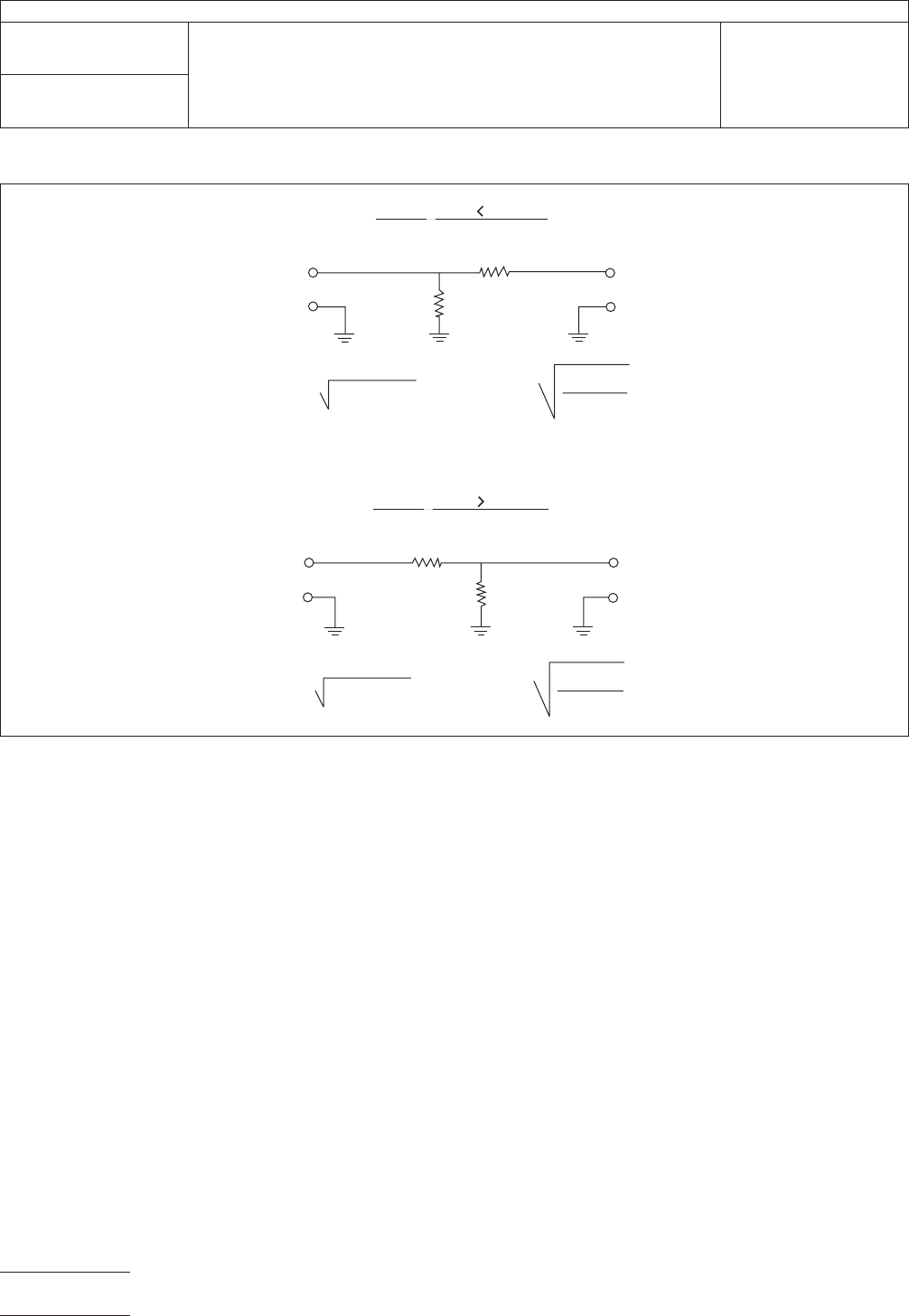
IPC-2-5-30-1
Figure
1 Resistive Matching Network for Unbalanced Cables
F
or Z System Z Cable:
Z System
R
1
R
2
F
or Z System Z Cable:
Z System
Z Cab
le
R
1
R
2
R =
1
Z
(Z - Z )
C
C
S
R =
Z
2
(Z - Z )
C
S
S
Z
S
R =
1
Z
(Z - Z )
C
R =
Z
2
(Z - Z )
C
S
Z
S
Z Cab
le
S
S
C
IPC-TM-650
Number
2.5.30
Subject
Balanced
and Unbalanced Cable Attenuation Measurements
Date
12/87
Revision
P
age2of4
电子技术应用 www.ChinaAET.com