IPC-TM-650 EN 2022 试验方法.pdf - 第486页
IPC-2257a-5-15 Figure 5-15 Measuring Amplitude for Incident Step -0.4 -0.3 -0.2 -0.1 0.0 0.1 0.2 0.3 0.4 Signal (V) Time t i,TS t f ,TS V open,Ch1 V open,Ch 2 Ch1 Ch2 V TS ,Ch2,1 V TS ,Ch1,1 -0.5 -0.6 t i,TL t f ,TL 0.5 …
Step
2 –
Probe
the reference airline using suitable adapter
and obtain a TDR waveform similar to that shown in Figure
5-16 for each channel. Measure the average voltage levels for
the high and low states for the two differential TDR wave-
forms, which are labeled V
TS,Ch1,2
, V
TS,Ch2,2
, V
std,Ch1
,
and
V
std,Ch2
in
Figure 5-16. There are a total of four states, two for
each of the differential waveforms. Calculate the voltage differ-
ence, V
r,Ch1
,
for Channel 1 (Ch1) using:
V
r,Ch1
= V
TS,Ch1,2
− V
std,Ch1
and
the voltage difference, V
r,Ch2
,
for Channel 2 (Ch2) using:
V
r,Ch2
= V
Ts,Ch2,2
− V
std,Ch2
where:
V
TS,Ch1,2
is
the average voltage level of that part of the Ch1
TDR waveform corresponding to the transfer standard (not
the same value as used in Step 1),
V
TS,Ch2,2
is
the average voltage level of that part of the Ch2
TDR waveform corresponding to the transfer standard (not
the same value as used in Step 1),
V
std,Ch1
is
the average voltage level of that part of the Ch1
TDR waveform corresponding to the reference standard (the
airline), and
V
lo,Ch2
is
the average voltage level of that part of the Ch2 TDR
waveform corresponding to the reference standard (the air-
line).
This calibration step can be performed using either one refer-
ence airline or two. Because the reference airline contains only
one signal conductor, if one airline is used, then calibration of
the two channels must be performed sequentially (in which
case, Figure 5-16 is a composite of two TDR waveforms, one
for each differential TDR channel). If two airlines are used, then
the calibration of the two channels can be performed simulta-
neously.
Step
3 –
Calculate
the characteristic impedance, Z
TS,Ch1
,o
f
the transfer standard for Channel 1 (Ch1) using:
Z
TS,Ch1
=
(
V
inc,Ch1
− V
r,Ch1
V
inc,Ch1
+ V
r,Ch1
)
Z
std
IPC-2257a-5-14
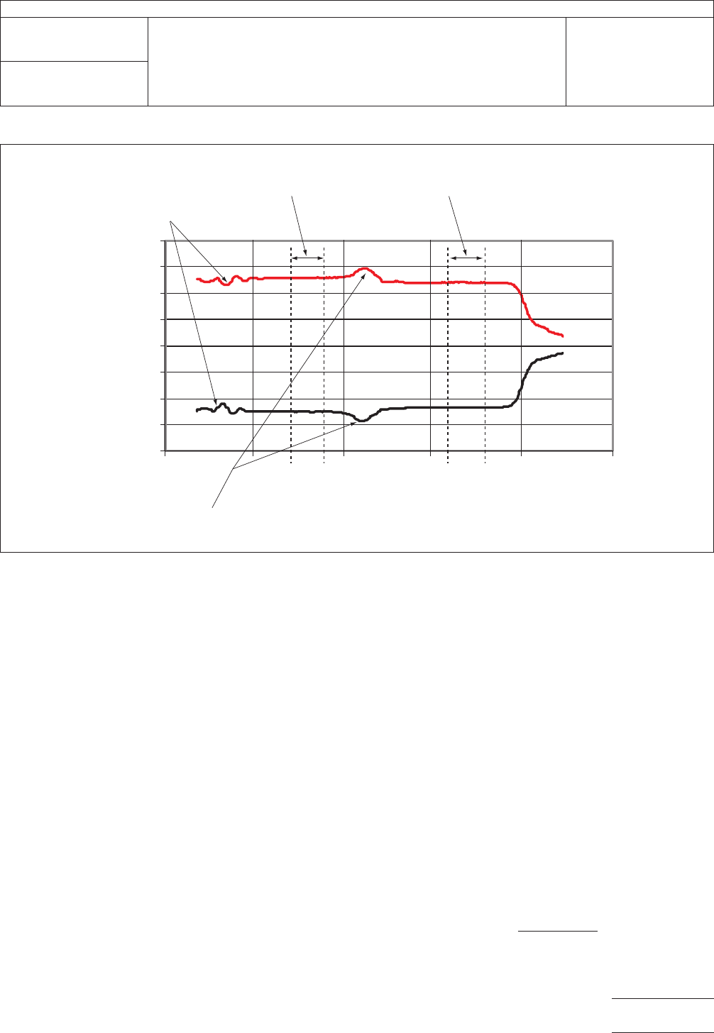
Figure
5-14 Measurement Zones for Differential TDR
-0.4
-0.3
-0.2
-0.1
0.0
0.1
0.2
0.3
0.4
Time
Signal (V)
Ch1
Ch2
TDR/Probe Interf
ace
Probe/T
ransmission Line Interface
T
ransfer Standard
Measurement Zone
T
ransmission Line
Measurement Zone
t
i,TS
t
i,TL
t
f
,TL
t
f
,TS
IPC-TM-650
Number
2.5.5.7
Subject
Characteristic
Impedance of Lines on Printed Boards by TDR
Date
03/04
Revision
A
Page
17 of 23
电子技术应用 www.ChinaAET.com
IPC-2257a-5-15
Figure
5-15 Measuring Amplitude for Incident Step
-0.4
-0.3
-0.2
-0.1
0.0
0.1
0.2
0.3
0.4
Signal (V)
Time
t
i,TS
t
f
,TS
V
open,Ch1
V
open,Ch
2
Ch1
Ch2
V
TS
,Ch2,1
V
TS
,Ch1,1
-0.5
-0.6
t
i,TL
t
f
,TL
0.5
0.6
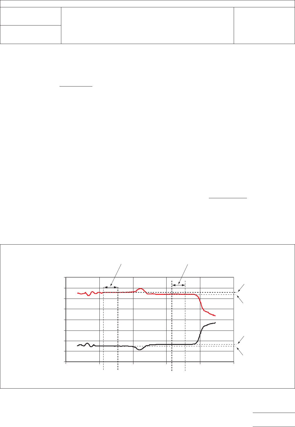
IPC-2257a-5-16
Figure
5-16 Calibration of Transfer Standard
-0.4
-0.3
-0.2
-0.1
0.0
0.1
0.2
0.3
0.4
Signal (V)
Time
V
TS
,Ch2,2
V
TS
,Ch1,2
t
i,TS
t
i,std
t
f
,std
t
f
,TS
Ch1
Ch2
V
std,Ch1
V
std,Ch2
IPC-TM-650
Number
2.5.5.7
Subject
Characteristic
Impedance of Lines on Printed Boards by TDR
Date
03/04
Revision
A
Page
18 of 23
电子技术应用 www.ChinaAET.com
and
the characteristic impedance, Z
TS,Ch2
,
of the transfer
standard for Channel 2 (Ch2) using
Z
TS,Ch2
=
(
V
inc,Ch2
− V
r,Ch2
V
inc,Ch2
+ V
r,Ch2
)
Z
std
where:
Z
std
the
characteristic impedance of the reference standard
(the airline).
5.3.4
Transmission Line Measurement Process
The
instrument
setting must be the same as that for 5.3.3. This
process should be done after the measure zone has been
defined (see 5.3.2).
Step
1 –
Probe
the transmission line and measure the aver-
age voltage levels for the high and low states for the two dif-
ferential TDR waveforms, which are labeled V
TS,Ch1,3
,
V
TS,Ch2,3
, V
TL,Ch1
,
and V
TL,Ch2
in
Figure 5-17. There are a total
of four states, two for each of the differential waveforms. Cal-
culate the voltage difference, V
r,Ch1,TL
for
Channel 1 (Ch1)
using:
V
r,TL,Ch1
= V
TS,Ch1,3
− V
TL,Ch1
and
the voltage difference, V
r,Ch2,TL
for
Channel 2 (Ch2) using:
V
r,TL,Ch2
= V
TS,Ch2,3
− V
TL,Ch2
where:
V
TS,Ch1,3
is
the average voltage level of that part of the Ch1
TDR waveform corresponding to the transfer standard (not
the same value as used in 5.3.3, Steps 1 and 2),
V
TS,Ch2,3
is
the average voltage level of that part of the Ch2
TDR waveform corresponding to the transfer standard (not
the same value as used in 5.3.3, Steps 1 and 2),
V
TL,Ch1
is
the average voltage level of that part of the Ch1 TDR
waveform corresponding to the transmission line under test,
and
V
TL,Ch2
is
the average voltage level of that part of the Ch2 TDR
waveform corresponding to the transmission line under test.
Step
2 –
Calculate
the odd-mode impedance, Z
odd,Ch1
,
for
the signal line of the transmission line under test connected to
Channel 1 (Ch1) using:
Z
odd,Ch1
=
(
V
inc,Ch1
− V
r,TL,Ch1
V
inc,Ch1
+ V
r,TL,Ch1
)
Z
TS,Ch1
and
the odd-mode impedance, Z
odd,Ch2
,
for the signal line of
the transmission line under test connected to Channel 2 (Ch2)
using:
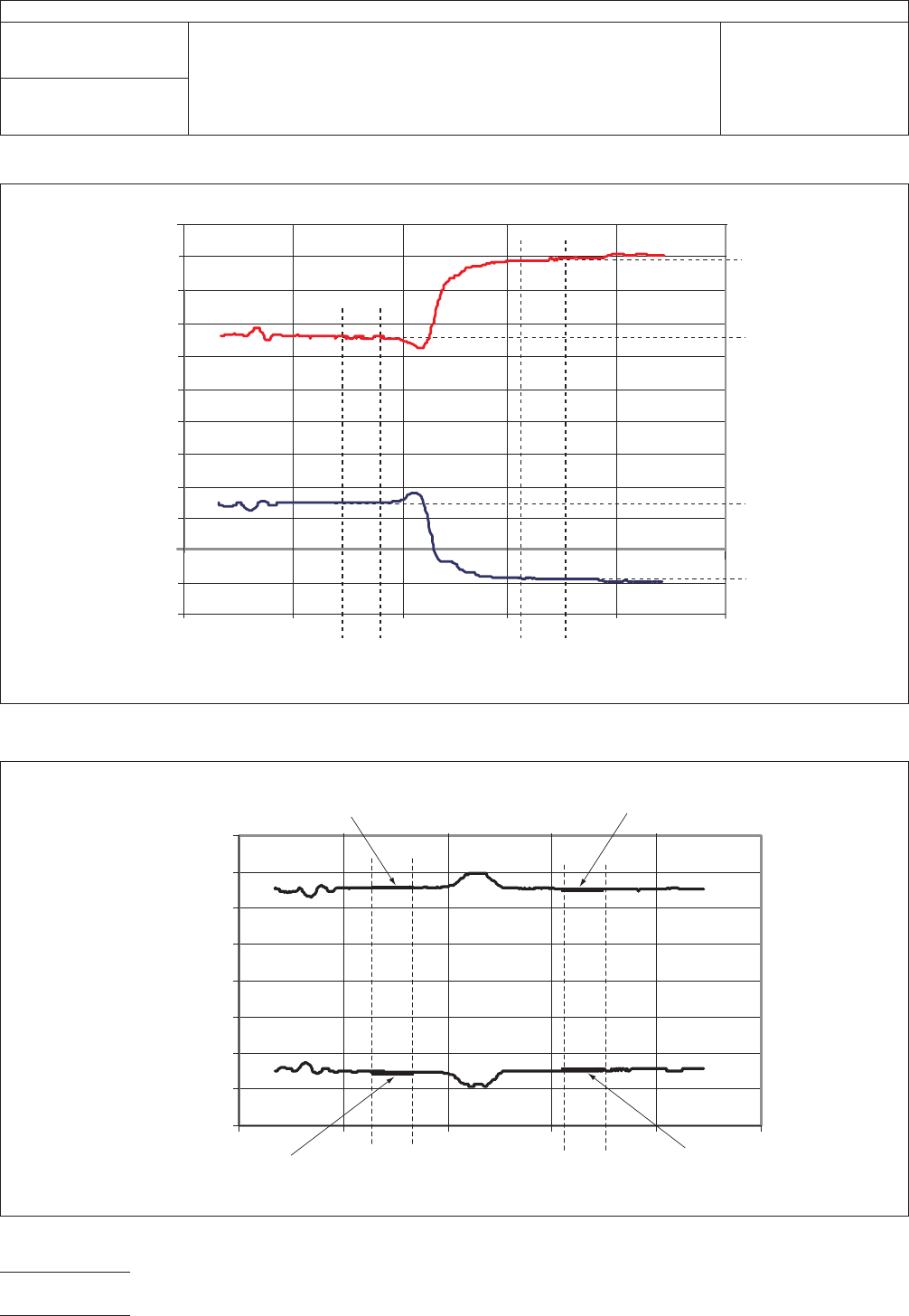
IPC-2257a-5-17
Figure
5-17 Differential TDR Measurement of Transmission Line
-0.4
-0.3
-0.2
-0.1
0.0
0.1
0.2
0.3
0.4
Signal (V)
Time
T
ransmission Line
Measurement Zone
t
i,TL
t
f
,TL
V
TL,Ch2
V
TL,Ch1
Ch2
Ch1
V
TS
,Ch2,
3
V
TS
,Ch1,
3
t
i,TS
t
f
,TS
Transfer Standard
Measurement Zone
IPC-TM-650
Number
2.5.5.7
Subject
Characteristic
Impedance of Lines on Printed Boards by TDR
Date
03/04
Revision
A
Page
19 of 23
电子技术应用 www.ChinaAET.com