IPC-TM-650 EN 2022 试验方法.pdf - 第473页
aberrations will increase the variation in the average voltage or reflection coefficient value from which Z 0 is computed, thereby increasing the variation in the compute value of Z 0 . 4.3 Other Equipment Requirements 4…
Intermediate
values can be linearly interpolated from Table 4-I
or using:
t
sys
≤
L
TL
2
1
v
p
For
example, if a 32 mm [1.26 in] long transmission line was
being measured, a TDR system with t
sys
≤ 80
ps should be
used. Note that, if the probe launch caused excessive ringing
in the TDR waveform, or if the launch does not repeatably
replicate the connection to the standard, then the 0.25 factor
may need to be smaller.
4.2
TDR Requirements
4.2.1 Impedance
The
impedance of the TDR unit should
be 50 Ω with an impedance uncertainty less than or equal to
± 0.5 Ω. This TDR impedance value is selected because it is
the impedance used by most high-speed/high-frequency test
instrumentation and compatibility with this instrumentation is
necessary for characterizing the dynamic TDR properties,
such as its impulse response (or transfer function). The imped-
ance of the TDR unit should be calibrated using an artifact
standard, such as an air line (see 4.3.6). However, the TDR
impedance is a function of frequency and calibration using a
fixed region of the TDR waveform (the measurement zone) will
only yield an average impedance value for the TDR unit for the
corresponding frequency range.
4.2.2
Timebase Accuracy
The
horizontal timebase accu-
racy defines how well the TDR instrument’s horizontal time
scale can display the correct length of the trace. This affects
both the accuracy of the measurement zone calculations and
any propagation delay values. The timebase accuracy should
be less than 0.25 t
sys
(see
also 4.1.2).
4.2.3
Step Aberrations
The
ability of the TDR instrument
to measure the impedance of a transmission line is related to
how well the instrument can generate a step-pulse with a
minimum of aberrations (ringing, overshoot, undershoot, set-
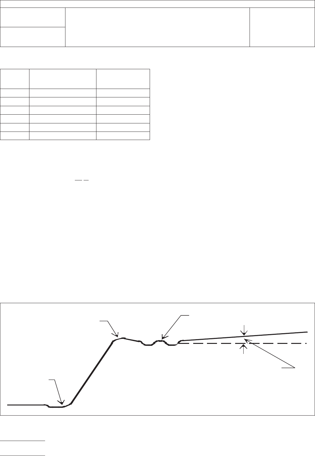
tling, etc.). Any ringing, overshoots, or undershoots will cause
corresponding aberrations in the TDR waveform (see Figure
4-2). These aberrations can cause significant errors in the
impedance value computed from the TDR waveform. Addi-
tionally, low frequency step aberrations may produce a ramp
in measurement zone. This ramp can cause a significant bias
in the computed impedance value. The TDR instruments step
aberrations should be less than 1% of the total step ampli-
tude. For example, the impedance error shown in Table 4-2 is
fora1mVerror of a 250 mV step. Poor settling and large
T
able 4-I Resolution of TDR Systems
TDR
System
Risetime
Resolution 4X Resolution
1
0ps 5ps/1mm[0.04 in] 4 mm [0.16 in]
20ps 10ps/2mm[0.08 in] 8 mm [0.31 in]
30ps 15ps/3mm[0.12 in] 12 mm [0.47 in]
100 ps 50 ps/ 10 mm [0.39 in] 40 mm [1.57 in]
200 ps 100 ps / 20 mm [0.79 in] 80 mm [3.15 in]
500 ps 250 ps / 50 mm [1.97in] 200 mm [7.87 in]
IPC-2257a-4-2
Figure
4-2 Potential TDR Step Aberrations
overshoot
undershoot
ringing
low frequency drift
IPC-TM-650
Number
2.5.5.7
Subject
Characteristic
Impedance of Lines on Printed Boards by TDR
Date
03/04
Revision
A
P
age4of23
电子技术应用 www.ChinaAET.com
aberrations
will increase the variation in the average voltage or
reflection coefficient value from which Z
0
is
computed, thereby
increasing the variation in the compute value of Z
0
.
4.3
Other Equipment Requirements
4.3.1 Connectors
TDR
systems typically come with either
‘‘SMA,’’ 3.5 mm, or 2.92 mm connectors at their measure-
ment ports. SMA, 3.5 mm, and 2.92 mm connectors are all
50 Ω connectors and are electrically and geometrically com-
patible, therefore, they can be mated directly to each other.
However, the 2.92 mm and 3.5 mm connectors are precision
connectors (have a lower impedance uncertainty than the
SMA) and are designed to provide a more repeatable connec-
tion than the SMA connector. Therefore, for accurate mea-
surements, it is recommended that the 2.92 mm or 3.5 mm
connector be used where possible. The bandwidth of the
connectors must be great enough so that the connectors do
not affect the accuracy of the TDR measurement. The typical
-3 dB bandwidth of 3.5 mm connectors is approximately
34 GHz and of SMA connector is approximately 24 GHz. The
reflection and insertion losses of the connector should be less
than 27 dB and 0.3 dB respectively. Other connectors, com-
parable in performance to the 3.5 mm connector, may also be
used. All cable connections using SMA, 3.5 mm, or 2.92 mm
connectors should be tightened with a torque wrench to fol-
lowing specification, unless otherwise specified by the manu-
facturer of the connector or cable:
4.3.2
Cabling
All
test cables should be coaxial and have a
characteristic impedance of 50 Ω with an impedance uncer-
tainty of less than ± 1 Ω. Cables used in the measurement
circuit of the transmission line under test should have connec-
tors that are compatible with the rest of the measurement
system. The bandwidth of the cable must be great enough so
that the cable does not affect the accuracy of the TDR mea-
surement. The length of the cables should be kept to a mini-
mum. The total insertion loss (including connector loss) of the
cabling connecting the transmission line under test to the TDR
should be kept to a minimum, for example, less than
0.033 dB/cm [1db/foot] at 26.5 GHz. Table 4-4 contains sug-
gested maximum cable lengths. Faulty cables can contribute
up to a 1 Ω error. Cable connections should be tightened with
a torque wrench to ensure a good connection.
4.3.3
Probes
The
probe assembly should have a charac-
teristic impedance of 50 Ω or of approximately the same value
as that of the transmission line under test, with an uncertainty
of ±1.0 Ω or less. The probe tips should be of sufficient diam-
eter and pitch (spacing between signal and ground tips) to
accurately and repeatably probe the desired probe contact
pad geometry. (See IPC-2141 for recommended probe land-
ing layouts for TDR coupons.) Single-ended probes should
contain two tips, one each for the signal and ground lines.
Differential probes should contain two tips for contacting the
signal lines and one or two tips for contacting the reference
plane or planes. The probe tips should have moderately sharp
edges to cut through any oxides. For hand held probe assem-
blies, the probe handle should be ergonomically shaped. The
probe bandwidth should be sufficient for the desired
temporal/spatial resolution (see 4.1.2). The probe settling time
should be short so as not to affect the duration of the mea-
surement zone. The overall performance of the probe can be
incorporated into the TDR system response for computing
TDR system temporal/spatial resolution (see 4.1.2). Inconsis-
tent probe force and placement is common and can cause a
significant yet unknown error that can exceed 5 Ω. Probe
connections should be tightened with a torque wrench to
ensure a good connection.
4.3.3.1
Probes for Differential Structures
The
differen-
tial probe should be long enough to act as a transfer stan-
dard, similar to that described in 4.3.7 for testing single-ended
T
able 4-2 Impedance Error
Impedance
Error
Transmission Line
Impedance
0.24 Ω 28 Ω
0.4 Ω 50 Ω
0.79 Ω 90 Ω
1.23 Ω 125 Ω
T
able 4-3 Connector Torque Specifications
[Conversion factor is 0.1128 N-m/(lb-in)]
Connector
Type Required Torque
SMA
0.56 N-m [5 lb-in]
3.5 mm
2.92 mm, K
0.9 N-m [8 lb-in]
Table 4-4 Maximum Suggested Cable Lengths
TDR
Cable Assembly TDR Cable Length
Sampling
Unit to Static Isolation Unit 30 cm [12 in]
Static Isolation Unit to In-Line
Secondary Standard
91 cm [36 in]
In-Line Standard (such as, semi-rigid
coaxial cable)
10 cm [4 in]
IPC-TM-650
Number
2.5.5.7
Subject
Characteristic
Impedance of Lines on Printed Boards by TDR
Date
03/04
Revision
A
P
age5of23
电子技术应用 www.ChinaAET.com
transmission
lines (see 5.2.1). This probe can be constructed
using a printed circuit board differential transmission line that
has a differential impedance similar to the traces being tested
or by using short identical lengths of semi-rigid cable that
connect the instrument cables to the differential probe. The
probe or semi-rigid cable should be sufficiently long to provide
an adequate duration for the measurement zone (see 4.1.2)
used during calibration and measurement.
4.3.4
Terminations
Many
instruments perform differently
under different electrical loads. If a test is performed with open
circuited lines, the calibration of the reference should also be
done using an open circuit termination.
4.3.5
ESD Protection
Static
build up on specimens prior
to test can damage the sampling heads in the TDR equip-
ment. Therefore, it is recommended that ESD protection be
used. Such protection can be supplied internally to the TDR
system or externally. If supplied externally, using a coaxial
switch for example, then the switch should be placed
between the transmission line under test and the TDR instru-
mentation. The switch, or static protection device (SPD),
should have a return and insertion loss less than 16 dB and
0.3 dB at 18 GHz. A maximum of 31 cm [12.2 in] of high
quality, high frequency cable may be used to connect the TDR
instrument to the protection switch. Samples should be
grounded to remove any residual static and/or passed
through some type of deionization device prior to testing.
Keeping the relative humidity in the test area between 45 %
and 55 % may minimize the buildup of static. Automation
software can be used to enhance the effectiveness of the
static isolation unit by switching the static isolation unit on/off
as required to minimize the amount of time that the TDR sam-
pling unit is exposed to potential ESD.
4.3.6
Calibration Artifacts (Reference or Reference
Standard)
A
precision coaxial air line with calibration trace-
able to a national metrology institute (such as the National
Institute of Standards and Technology), 3.5 mm or 2.92 mm
connectors at both ends, and at least 10 cm [3.94 in] long
should be used. The characteristic impedance of the air line is
based on the geometry of a coaxial transmission line using air
as the dielectric between the center conductor (signal line)
and the ground shield. The center conductor may be held in
place by glass beads located at both ends of the air line or by
the external connectors that are attached to the connectors of
the air line. The uncertainty in the nominal characteristic
impedance of the air line should be less than or equal ±
0.015 Z
ref
, where Z
ref
is
the characteristic impedance of the
reference air line.
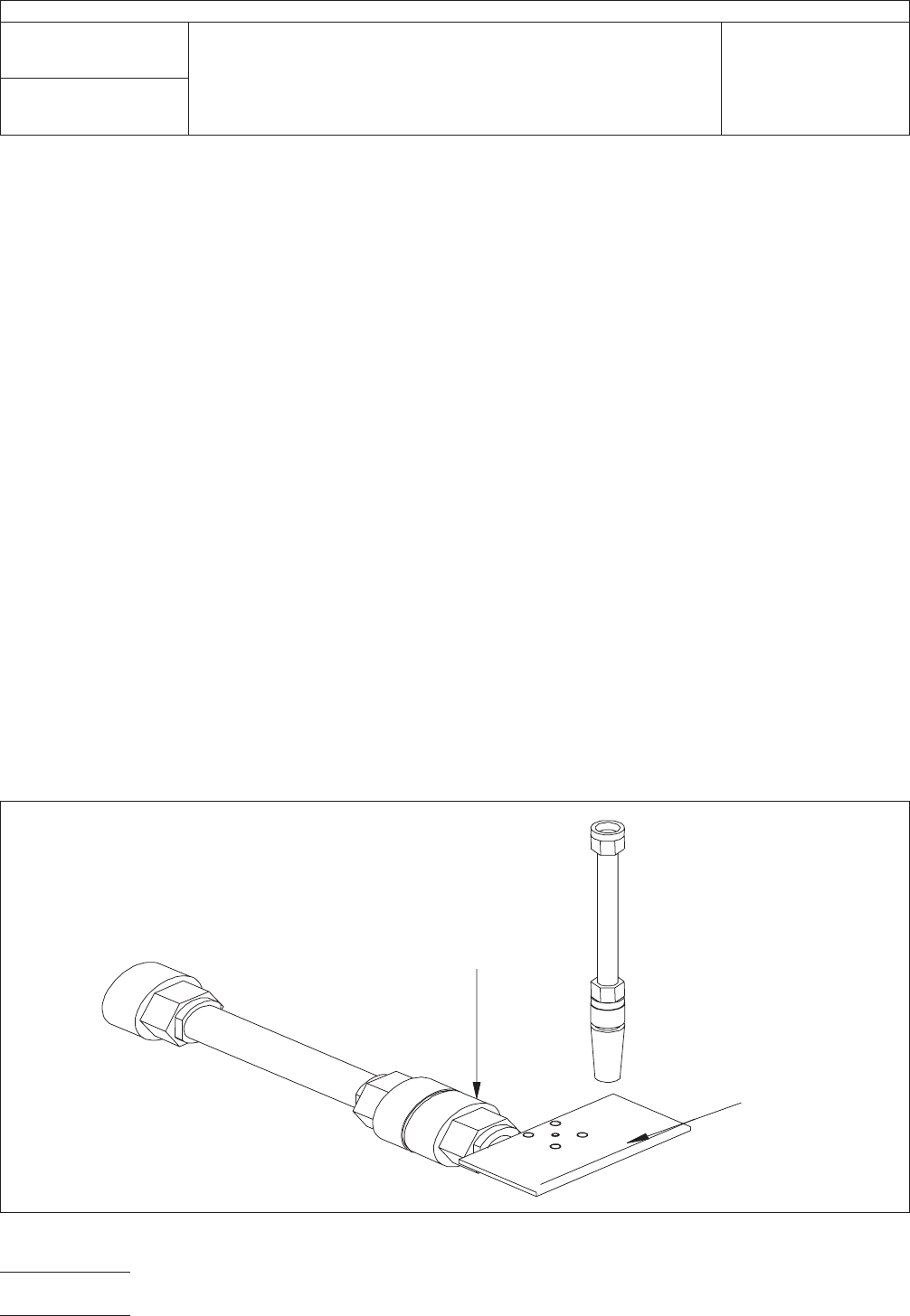
4.3.7
In-Line (Transfer) Standard
The
transfer standard
is placed between the probe and the TDR unit (see Figure
4-3). This standard could be an airline, a semi-rigid coax cable
assembly with the same specifications as the flexible coax
cable assemblies, or other. The transfer standard should be of
IPC-2257a-4-3
Figure
4-3 Reference Airline and Probe Contact Pad
REFERENCE
AIRLINE
PROBE
TRANSFER
STANDARD
PROBE
CONTACT
PAD
ADAPTOR
IPC-TM-650
Number
2.5.5.7
Subject
Characteristic
Impedance of Lines on Printed Boards by TDR
Date
03/04
Revision
A
P
age6of23
电子技术应用 www.ChinaAET.com