IPC-TM-650 EN 2022 试验方法.pdf - 第358页
T able 2 Initial Stackweight (Wo, grams) vs. Calculated Initial Thickness (ho, mils) 104 106 108 112 113 116 7628 Wo ho Wo h o Wo ho Wo h o Wo ho Wo h o Wo ho 20 1.03 25 1.28 40 1.95 35 3.13 35 2.97 45 3.82 80 6.71 21 1.…
4.7
Unless
otherwise specified, press the specimen with a
force of 840 lb (31.0 psi) ± 5% for 10 minutes minimum. Full
force is to be applied within 15 seconds after sample is placed
on the press plate.
4.8
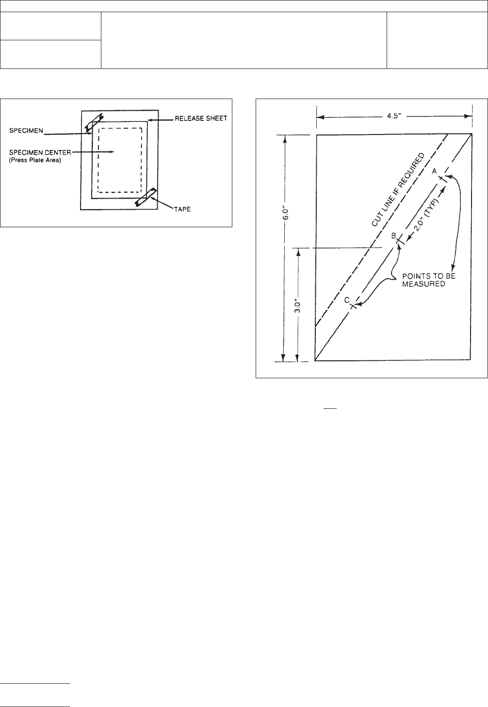
Carefully
remove the hot specimen from the press, flip
over onto a smooth flat surface and cool for 5 minutes or to a
rigid state before making measurements.
4.9
Remove
release material from stack. Using the template
shown in Figure 2, mark the points to be measured. Cut the
stack when required to facilitate measuring the specific points
along the cut line shown in Figure 2.
5.0
Test Results
5.1
Measure
the thickness to the nearest 0.0001 inch with a
micrometer at the three intervals defined by the template.
Record all three measurements for each test specimen. If
there is a thickness variation between the three measure-
ments of 0.003 inches or more, the test must be repeated.
Average the three measurements to determine final measured
thickness.
5.2
Use
the initial weight, WO, to determine the initial thick-
ness (Ho) either from the formula in Appendix or from Table 2.
5.3
Final
thickness per ply can be calculated by dividing the
final measured thickness by the number of plies. Initial thick-
ness and final thickness can be used to calculate thickness
change.
Appendix
Determination
of Initial Thickness: (See Table 2)
ho =
F
Wo
n
(5.54
x 10
−2
)−
G
2.12
x 10
−2
Where:
ho
= Initial thickness per ply (mils)
Wo = Initial stack weight (g)
Wg = Unit glass weight (g/in2)
n = Number of plies
Unit Glass Weights: (Approximated from test results)
Style
104
106
108/1080
112/2112
113/2113
116/2116
7628
Weight (g/in2)
0.0128
0.0164
0.0311
0.0464
0.0538
0.0691
0.1312
IPC-2438-1
Figure
1
IPC-2438-2
Figure
2
IPC-TM-650
Number
2.4.38
Subject
Prepreg
Scaled Flow Testing
Date
6/91
Revision
A
P
age2of3
电子技术应用 www.ChinaAET.com

T
able 2 Initial Stackweight (Wo, grams) vs. Calculated Initial Thickness (ho, mils)
104
106 108 112 113 116 7628
Wo ho Wo ho Wo ho Wo ho Wo ho Wo ho Wo ho
20 1.03 25 1.28 40 1.95 35 3.13 35 2.97 45 3.82 80 6.71
21 1.10 26 1.35 41 2.02 36 3.24 36 3.09 46 3.94 81 6.73
22 1.16 27 1.41 42 2.08 37 3.36 37 3.21 47 4.06 82 6.85
23 1.23 28 1.48 43 2.15 38 3.48 38 3.32 48 4.17 83 6.97
24 1.29 29 1.54 44 2.21 39 3.60 39 3.44 59 4.29 84 7.08
25 1.36 30 1.61 45 2.28 40 3.71 40 3.56 50 4.41 85 7.20
26 1.43 31 1.68 46 2.34 41 3.83 41 3.67 51 4.52 86 7.32
27 1.49 32 1.74 47 2.41 42 3.95 42 3.79 52 4.64 87 7.44
28 1.56 33 1.81 48 2.47 43 4.07 43 3.91 53 4.76 88 7.55
29 1.62 34 1.87 49 2.54 44 4.18 44 4.03 54 4.88 89 7.67
30 1.69 35 1.94 50 2.60 45 4.30 45 4.14 55 4.99 90 7.79
31 1.75 36 2.00 51 2.67 46 4.42 46 4.26 56 5.11 91 7.91
32 1.82 37 2.07 52 2.73 47 4.54 47 4.38 57 5.23 92 8.02
33 1.88 38 2.13 53 2.80 48 4.65 48 4.50 58 5.35 93 8.14
34 1.95 39 2.20 54 2.86 49 4.77 49 4.61 59 5.46 94 8.26
35 2.01 40 2.26 55 2.93 50 4.89 50 4.73 60 5.58 95 8.38
36 2.08 41 2.33 56 2.99 51 5.01 51 4.85 61 5.70 96 8.49
37 2.14 42 2.39 57 3.06 52 5.12 52 4.97 62 5.82 97 8.61
38 2.21 43 2.46 58 3.13 53 5.24 53 5.08 63 5.95 98 8.73
39 2.27 44 2.52 59 3.19 54 5.36 54 5.20 64 6.05 99 8.85
40 2.34 45 2.59 60 3.26 55 5.48 55 5.32 65 6.17 100 8.96
41 2.40 46 2.65 61 3.32 56 5.59 56 5.44 66 6.29 101 9.08
42 2.47 47 2.72 62 3.39 57 5.71 57 5.55 67 6.40 102 9.20
43 2.53 58 2.78 63 3.45 58 5.83 58 5.67 68 6.52 103 9.32
44 2.60 59 2.85 64 3.52 59 5.95 59 5.79 69 6.64 104 9.43
45 2.66 50 2.91 65 3.58 60 6.06 60 5.91 70 6.76 105 9.55
Wo = grams, ho = mils; (n) for 104, 106, 108 = 18; (n) for 112, 113, 116 7628 = 10
Reference Documents
1. Journal of Elastomers and Plastics, 10,367 (1978), C.J. Bartlett
2. Journal of Elastomers and Plastics, 10,365 (1978) D.P. Bloechle
3. IPC-TP-281, The Use of Scaled Flow Testing for B-Stage Prepreg, C.J. Bartlett, D.P. Bloechle, W.A. Mazeika
4. IPC-TP-418, Application of Scaled Flow Testing as an Incoming Inspection Criteria, H.J. Brown
5. IPC-TP-420, Scaled Flow for Testing CRC Prepreg, J. Del, P. Marx, J. Sallo
6. D.P. Bloechle, ‘‘Epoxy Prepreg Characterization using Scaled Flow Testing Techniques,’’ Circuit World, 9,1 (1982), p.8
IPC-TM-650
Number
2.4.38
Subject
Prepreg
Scaled Flow Testing
Date
6/91
Revision
A
P
age3of3
电子技术应用 www.ChinaAET.com
1.0
Scope
This
procedure defines a test method used to
determine dimensional stability of glass reinforced, copper-
clad, thin laminates intended for use in rigid multilayer printed
boards.
The test is appropriate for checking material consistency. It is
not intended for defining suitability of the raw material to be
used in a specific printed board product or process.
2.0
Applicable Documents
IPC-TR-483
‘‘Dimensional
Stability Testing of Thin Lami-
nates’’
3.0
Test Specimen
The
specimen shall be 300 mm x 280
mm [12 in x 11 in] in size with the warp direction in the 300
mm dimension. A minimum of three specimens is required per
inspection lot. When evaluating laminate sheets, specimens
should be taken from opposite diagonal corners and from the
center of the sheet. For precut panels three randomly selected
panels shall be used to obtain the test specimens.
4.0
Apparatus
4.1
The
measurement apparatus shall be capable of mea-
suring the specimen within an accuracy of 0.0125 mm
[0.0005 in], over 250 mm [10.0 in] dimension. (Supergauge, or
equivalent, may be used.)
4.2
Ovens
used for baking must be of the air circulating type
and capable of ± 2°C control. The recovery time of the tem-
perature must be less than 15 minutes after specimens are
placed in the oven.
4.3
A
stabilization chamber (drying cabinet) containing cal-
cium chloride or silica gel capable of maintaining less than 20
RH at 21 ± 2°C.
5.0
Test Procedure
5.1 Preparation of the Specimen
5.1.1
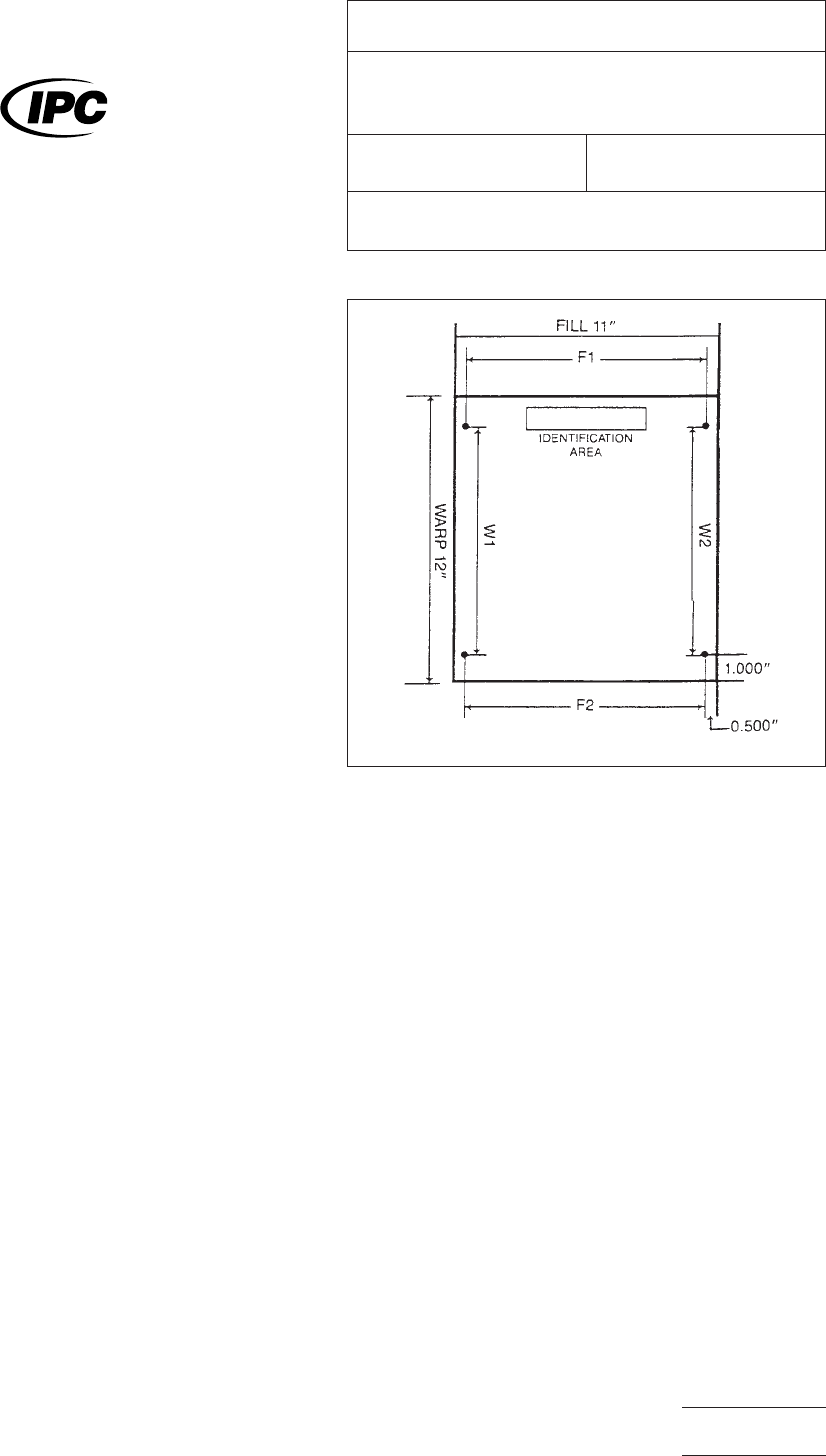
Mark
the specimen for traceability in the identification
area (see Figure 1). No mechanical or chemical pre-cleaning is
permitted on the specimen.
5.1.2
Prepare
the four location points (see Figure 1) by drill-
ing or scribing.
5.1.3
Measure
distances Fl, F2, W1, and W2 utilizing the
apparatus defined in paragraph 4.1. Define distances to the
nearest 2.5 microns [0.0001 in]; the last digit of the reading
may be estimated. Record all values as initial measurements.
5.1.3.1
If
optical measurement must be used, a rigid plate
shall maintain the test specimen in a flat and horizontal posi-
tion.
5.1.4
Place
a 12 mm [0.5 in] diameter tape dot over holes
or scribe marks on side of laminate to be measured and a
piece of 25 mm x 12 mm [1.0 in x 0.5 in] wide tape over iden-
tifying information.
IPC-2439-a
Figure
1 All dimensions are in inches. Four
measurements are required as indicated. Locate
measuring points approximately 12.7mm [0.500 in] from
each edge in the fill direction, and 25.4 mm [1.00 in] from
each edge in the warp direction.
The
Institute for Interconnecting and Packaging Electronic Circuits
2215 Sanders Road • Northbrook, IL 60062-6135
IPC-TM-650
TEST
METHODS MANUAL
Number
2.4.39
Subject
Dimensional
Stability, Glass Reinforced Thin
Laminates
Date
2/86
Revision
A
Originating Task Group
N/A
Material
in this Test Methods Manual was voluntarily established by Technical Committees of the IPC. This material is advisory only
and its use or adaptation is entirely voluntary. IPC disclaims all liability of any kind as to the use, application, or adaptation of this
material. Users are also wholly responsible for protecting themselves against all claims or liabilities for patent infringement.
Equipment referenced is for the convenience of the user and does not imply endorsement by the IPC.
P
age1of3
电子技术应用 www.ChinaAET.com