Operating Instructions_VF335_en.pdf - 第103页
5|Commissioning NOTE Why are the [Positioning] and [Special positions] frames not displayed? a) This can have several causes: ð Your machine does not have a program-controlled width adjustment. ð The program-controlled…
5|Commissioning
ð If the actual values correspond to the entered set values, referencing is com-
plete
5.3.9.2 Referencing the soldering module
ü To reference the soldering module, proceed as follows:
a) In the start dialog in the [Soldering] frame, click on the symbol of the soldering
module.
ð The [Soldering unit 1 Solder pot 1] input dialog is opened.
b) In the [Special positions] frame, click on the
button to start the referencing
process.
c) Repeat the procedure with all available soldering modules.
d) The process has now been completed.
NOTE
The travel movement requires a certain amount of time.
a) In the meantime, do not perform any inputs.
b) During referencing, the
symbol is displayed next to a moving axis in the setting
dialog.
ü Checking the X and Y positions:
a) Compare the actual values with the entered set values.
b) Readjust any deviation Then repeat referencing.
ð If the actual values correspond to the entered set values, referencing is com-
plete
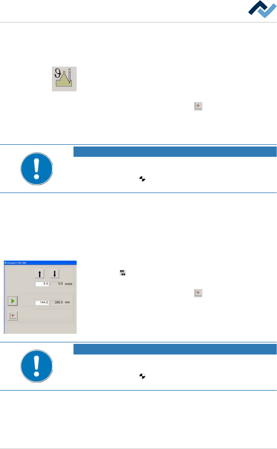
5.3.9.3 Referencing width adjustment
Conveyor width adjustment
Positioning
Set value Actual value
Set value Actual value
Step mode
Special positions
v
ü Width adjustment can be referenced as follows:
a) Click on the
button in the start dialog.
ð The [Conveyor width adjustment] input dialog is opened.
b) In the [Special positions] frame, click on the
button.
ð The referencing process is started.
NOTE
The travel movement requires a certain amount of time.
a) In the meantime, do not perform any inputs.
b) During referencing, the
symbol is displayed next to a moving axis in the setting
dialog.
a) Measure the actual distance between the two conveyor rails and compare the
result with the displayed actual value. If the measured value does not corres-
pond with the displayed value, the width adjustment must be adjusted.
Ersa GmbH Operating Instructions_VF335_en|Rev. 14|30/11/2017 102/695

5|Commissioning
NOTE
Why are the [Positioning] and [Special positions] frames not displayed?
a) This can have several causes:
ð Your machine does not have a program-controlled width adjustment.
ð The program-controlled width adjustment has not been configured.
ð The [Enable only step mode] checkbox is enabled in the settings dialog.
Ersa GmbH Operating Instructions_VF335_en|Rev. 14|30/11/2017 103/695

5|Commissioning
5.3.10 Check modules
5.3.10.1 Check the conveyor system
ü The following tasks must be performed:
a) Check the entire conveyor system for parallelism and adjust if necessary.
b) Check the drives for proper operation. For this purpose, in the start dialogue,
click on the
button to start all conveyors together. When the conveyors are
running, the button is displayed in yellow.
ð The process has now been completed.
Ersa GmbH Operating Instructions_VF335_en|Rev. 14|30/11/2017 104/695