Operating Instructions_VF335_en.pdf - 第647页
9|Spare and wear parts Pos Description Item number A B 6 Box spanner SW13 (without illustration) 6ISK582005 x View [Y] A A A 2 1 A A Fig.363: EM146-61-10-00a Pos Description Item number A B 1 Plate heating element 1.4…
9|Spare and wear parts
9.9.2.2 DIP soldering module (multiwave) standard pressure chamber and solder
pot
Overview
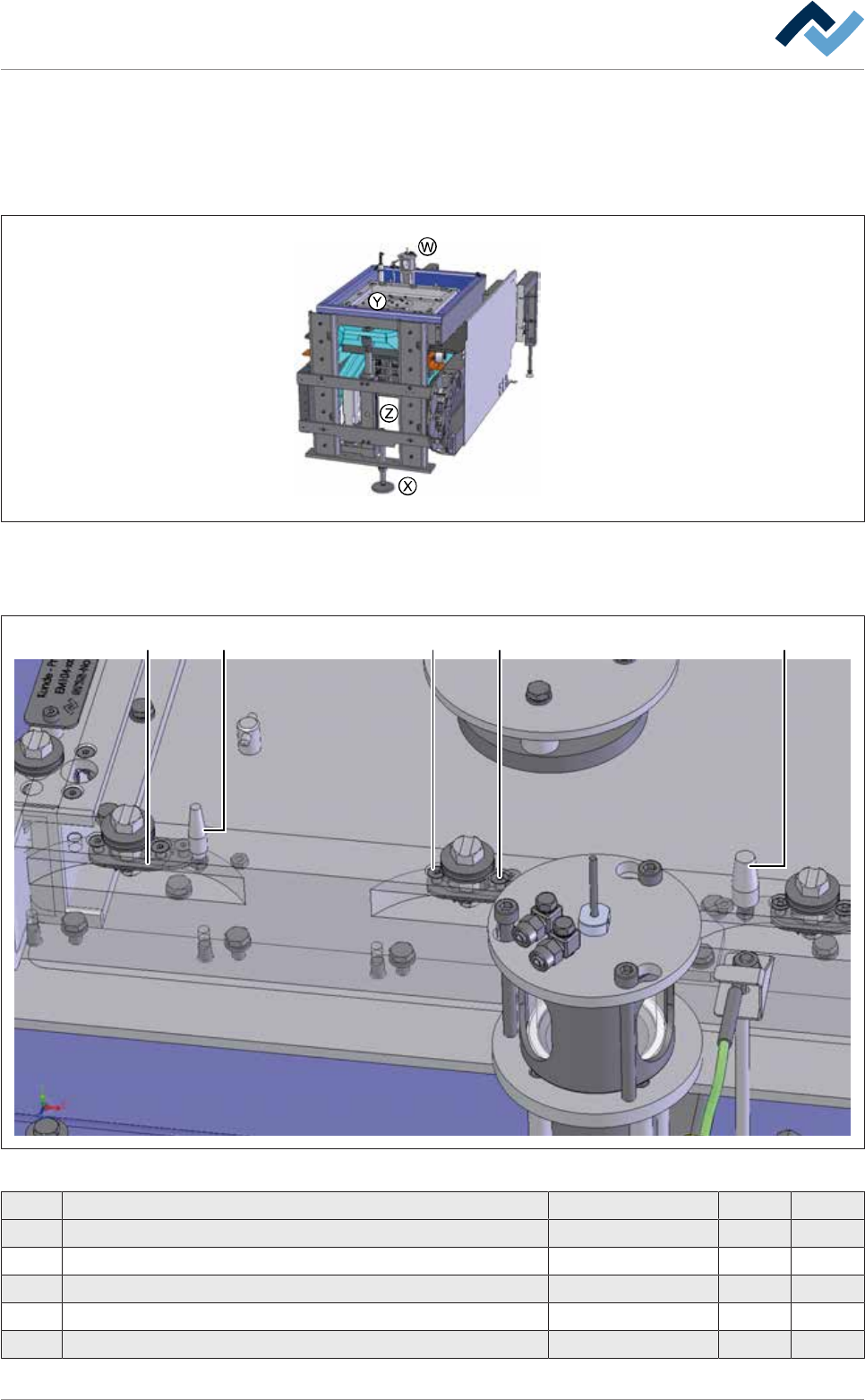
Fig.361: EM131-61-00b
View [Y]
3 4 41 2
Fig.362: EM131-61-00c
Pos Description Item number A B
1 Fixing bolt, long, Ø = 8 mm 216359 x
2 Fixing bolt, long, Ø = 12 mm 216360 x
3 Bajonet cap, bottom part 139072 x
4 Countersunk screw 102588 x
5 Extraction tool for solder nozzles (without image) 12555 x
Ersa GmbH Operating Instructions_VF335_en|Rev. 14|30/11/2017 646/695
9|Spare and wear parts
Pos Description Item number A B
6 Box spanner SW13 (without illustration) 6ISK582005 x
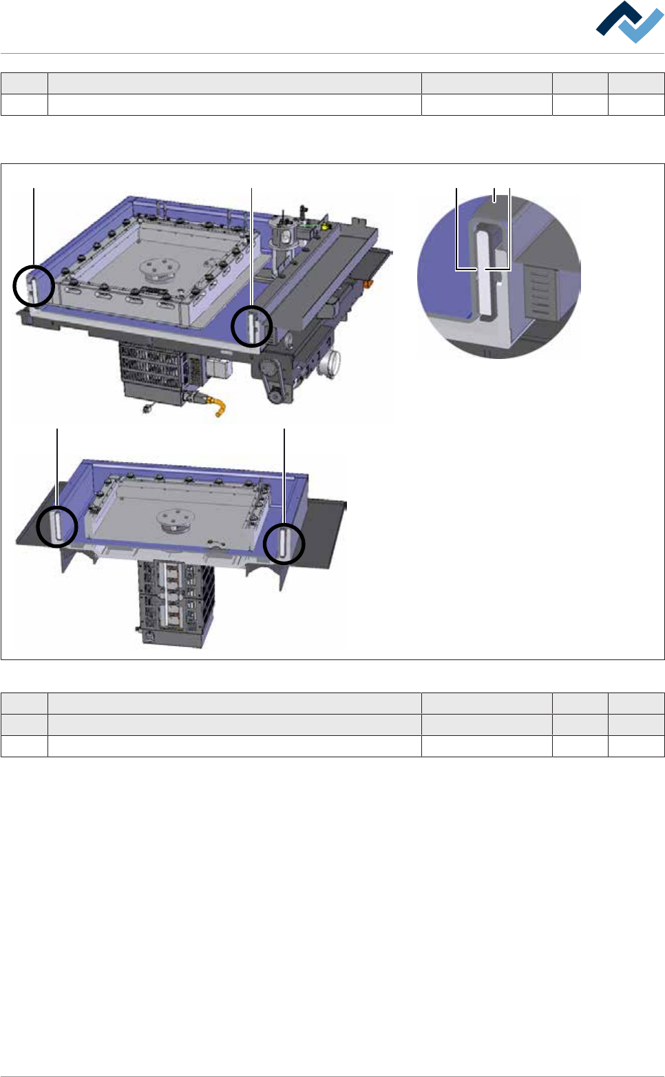
View [Y]
A AA 21
A A
Fig.363: EM146-61-10-00a
Pos Description Item number A B
1 Plate heating element 1.4 kw, 230 V 203919 x
2 Insulating 470x85x12 perforated 203917 x
Ersa GmbH Operating Instructions_VF335_en|Rev. 14|30/11/2017 647/695
9|Spare and wear parts
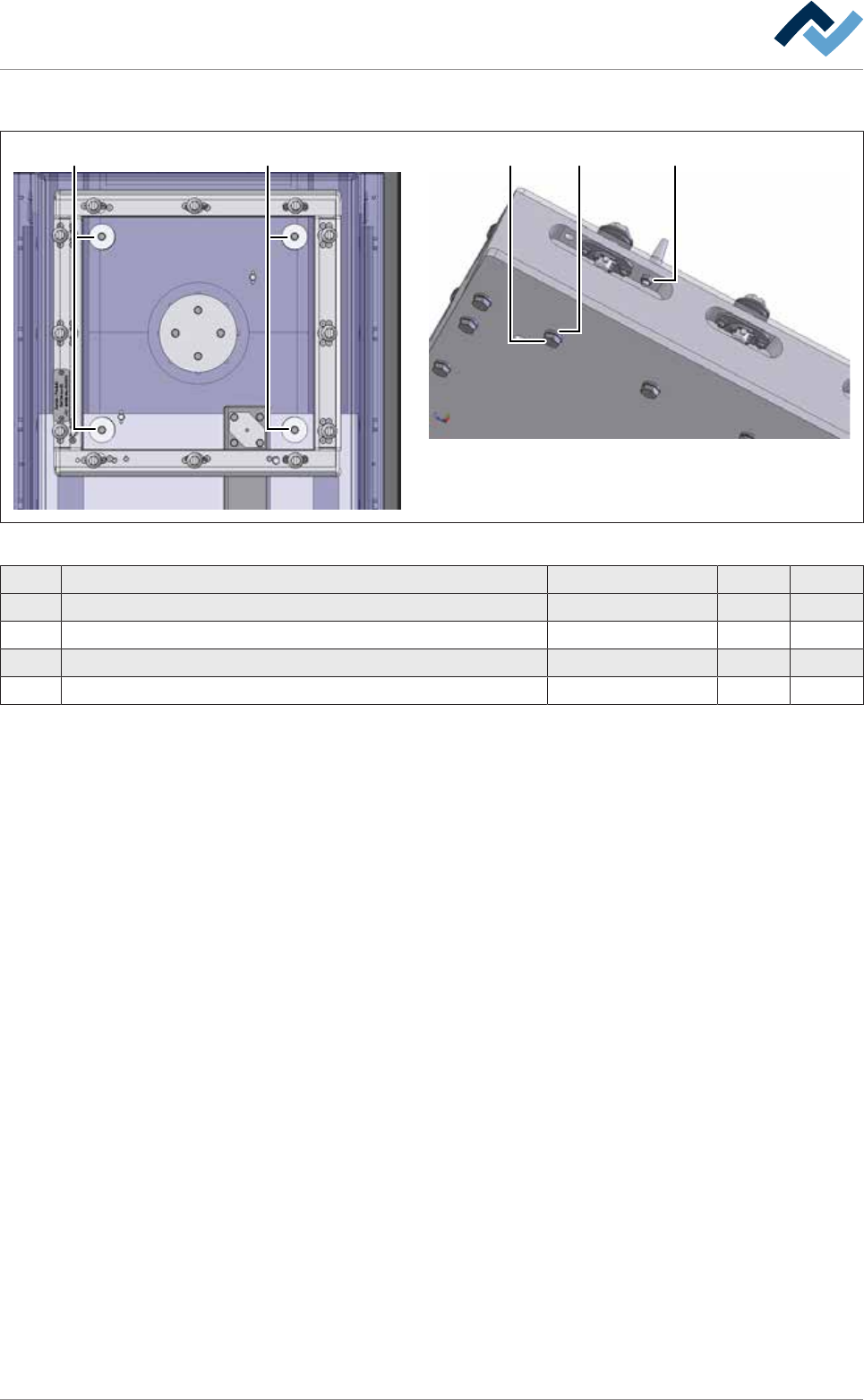
View [Y]
1 1 2 3 4
Fig.364: EM131-61-00d
Pos Description Item number A B
1 Graphite sealing 91957 x
2 Hexagonal screw M6x16 DIN 933 203601 x
3 Washer U06,4 QPQ DIN 125B 203600 x
4 Hexagonal nut 91248 x
Ersa GmbH Operating Instructions_VF335_en|Rev. 14|30/11/2017 648/695