Operating Instructions_VF335_en.pdf - 第231页
6|Function description 6.14.1 Infeed and infeed unit We distinguish between infeed and infeed unit . Please note: A module is always provided with a conveyor. An infeed has, for example, a sensor, a (virtual) barrier o…
6|Function description
Each module is schematically displayed with a symbol. However, a unit is only dis-
played in the start dialog if it has been marked as available in the configuration of
the machine. A module can also be repeatedly available as, for example, in the case
of preheaters or soldering modules.
If you move your mouse on a module, a short explanation (tooltip) is displayed. In
the [Maintenance mode] operating mode, you can enable units, enter set values
and read actual values. An activated module changes its colour in the start dialog
from grey to yellow.
The icons and buttons in the bottom toolbar have the following meaning:
[Conveyor width adjustment ]: It opens the editing dialog of the conveyor width ad-
justment.
All conveyors on. Click on this button to switch on all the machine conveyors simul-
taneously. If a conveyor is switched on, this button is displayed in yellow.
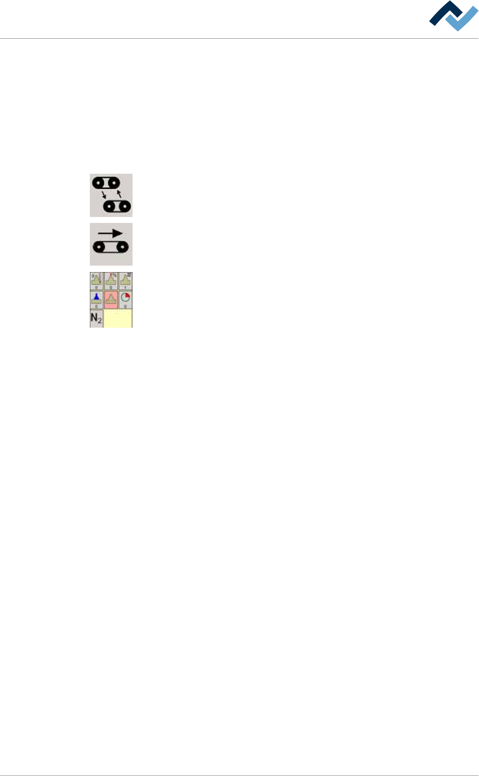
The following buttons are always combined in groups and open - after being clicked
on - the editing dialog of the module. In the example shown, you can see the but-
tons of a soldering unit. Here, the buttons schematically display, for example, the
pot, solder wave, nozzle number or protective gas supply. For a quick overview
without having to open the input dialog, actual values can be read at the bottom of
the buttons.
Ersa GmbH Operating Instructions_VF335_en|Rev. 14|30/11/2017 230/695
6|Function description
6.14.1 Infeed and infeed unit
We distinguish between infeed and infeed unit. Please note: A module is always
provided with a conveyor.
An infeed has, for example, a sensor, a (virtual) barrier on the inline interface and a
code reader, but no conveyor.
An infeed unit is provided with a conveyor and a mechanical barrier.
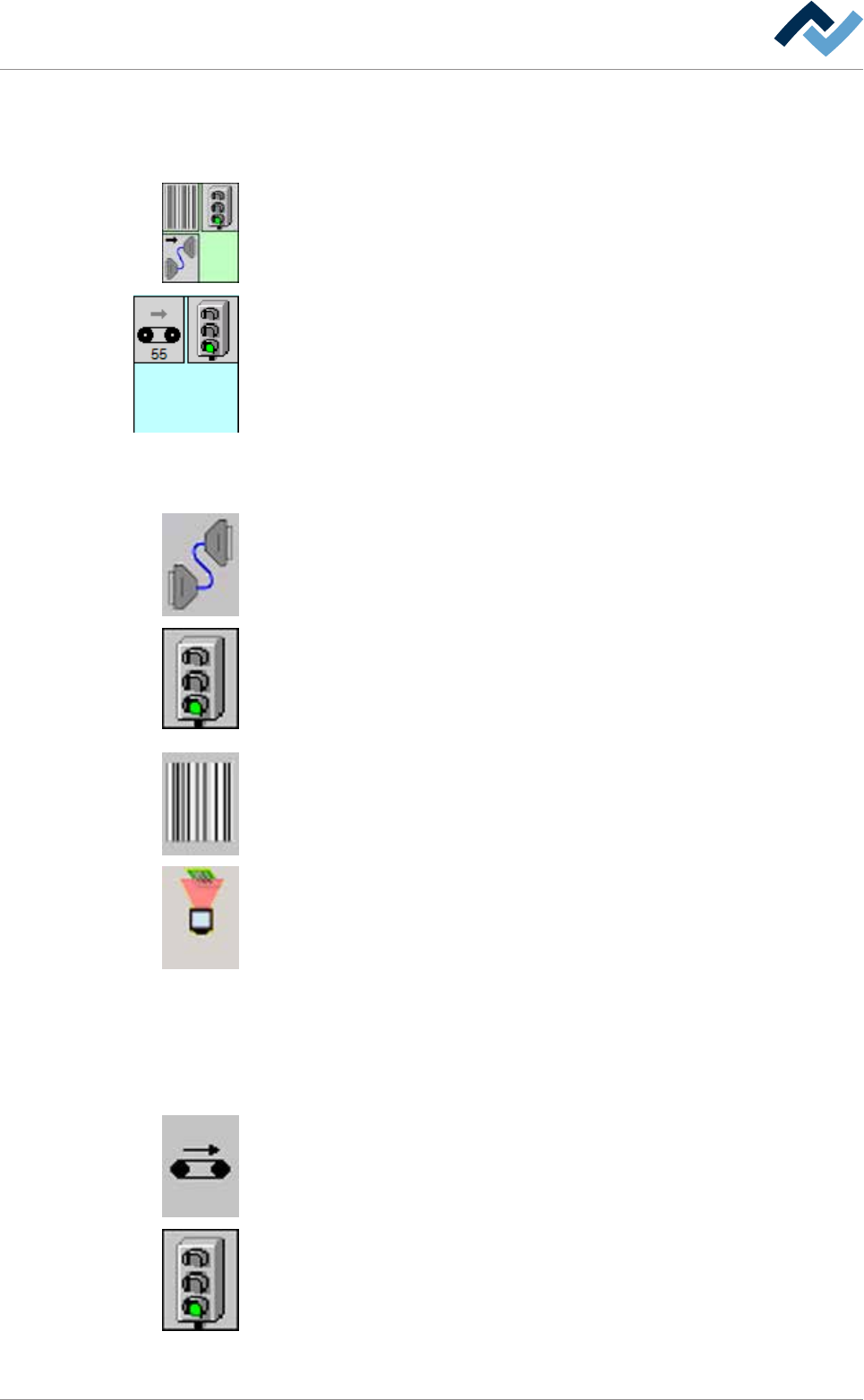
Infeed
The following buttons can be available; by clicking on them, you can open the [In-
feed] input dialog:
Inline interface It shows if an inline interface is available.
(Virtual) infeed barrier This button is only displayed in the [Automatic mode] oper-
ating mode.
It shows the status of the infeed barrier. Red light: It signals the upstream system
that the machine cannot accept any boards. Green light: It signals the downstream
system that the machine is ready to accept boards.
Code mode As soon as the code mode is active, this button is displayed in yellow.
Code reader With an active code reader, the button is displayed in yellow.
Infeed unit
The following buttons can be available; by clicking on them, you can open the [In-
feed] input dialog:
Conveyor. When the conveyor is running, this button is displayed in yellow.
(Mechanical) barrier: Green light: The barrier in the module is open. Red light: The
barrier in the module is closed.
Ersa GmbH Operating Instructions_VF335_en|Rev. 14|30/11/2017 231/695
6|Function description
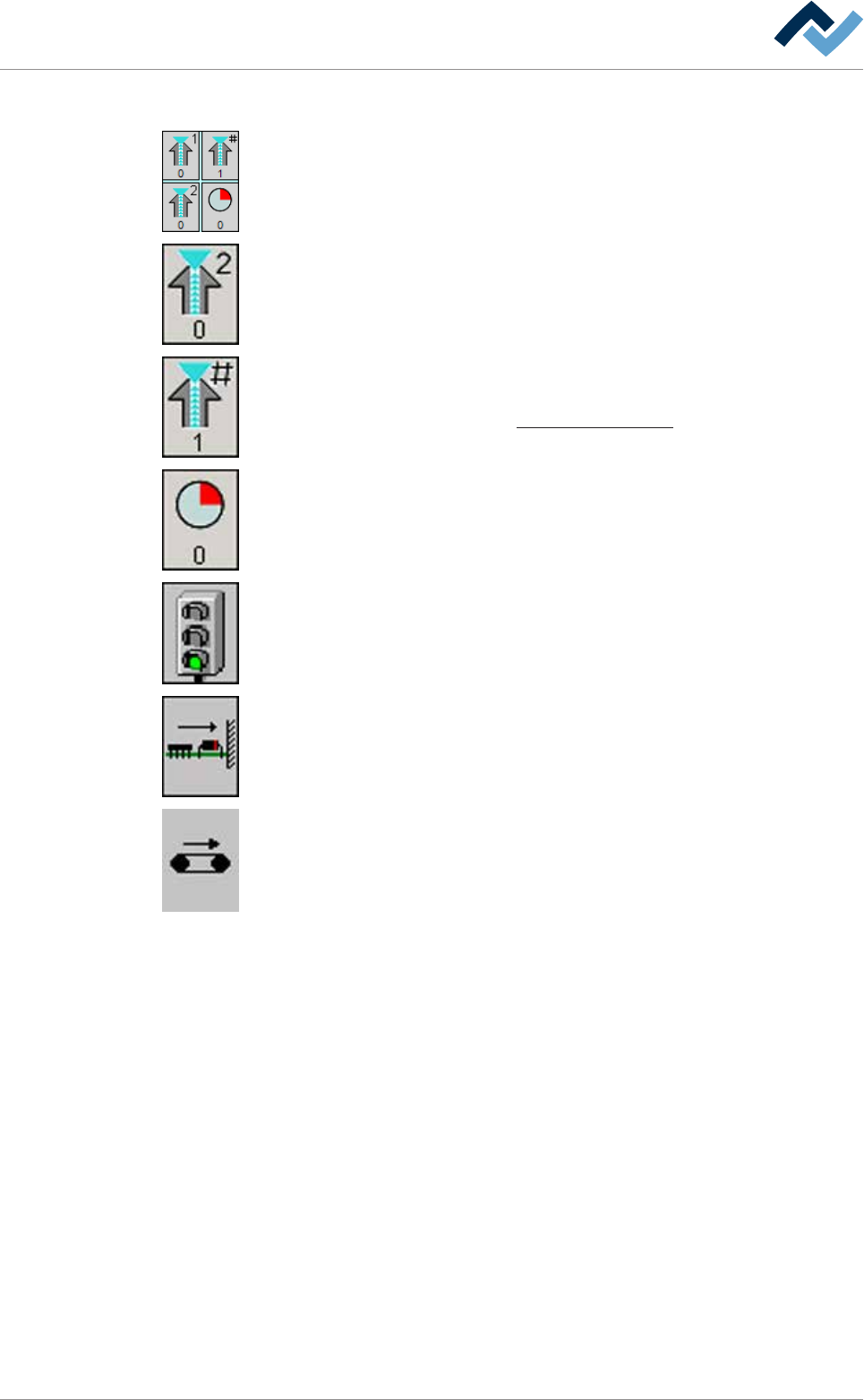
6.14.2 Flux module
The following buttons can be available; by clicking on them, you can open the input
dialog of the flux module:
Spray head. When the spray head is active, this button is displayed in yellow. For
each spray head, a separate button is available. The number of the spray head can
be read in the top section. The current dosing can be read as a [%] in the bottom
section.
Active spray head combination The number of the nozzle which has been activated
in the nozzle table is displayed in the bottom section.
On this regard, please read Chapter Fluxer unit data sets [
}188].
Remaining time in the module. You can read the remaining processing time in the
bottom section. Time runs backwards as soon as the board is processed in the
module.
(Mechanical) barrier: Green light: The barrier in the module is open. Red light: The
barrier in the module is closed.
Board horizontal fixing If fixing is active, this button turns yellow.
Conveyor. When the conveyor is running, this button is displayed in yellow.
Ersa GmbH Operating Instructions_VF335_en|Rev. 14|30/11/2017 232/695