Operating Instructions_VF335_en.pdf - 第218页
6|Function description 6.12 Machine operating modes The machine operating modes are shown on the next page. Ersa GmbH Operating Instructions_VF335_en|Rev. 14|30/11/2017 218/695
6|Function description
NOTE
Why cannot a soldering program be started?
If a soldering program cannot be started, several causes are possible:
ü The machine is in the [Maintenance mode] operating mode.
ü Referencing of a module is not OK.
ü The machine is not empty, there are still boards inside it.
ü The transition to [Automatic mode] is not allowed and will be prevented.
a) In this case, open the [Messages] dialog.
b) Eliminate the specified problems and acknowledge the messages.
c) Set the machine to the [Maintenance mode] operating mode.
d) Restart the soldering program.
NOTE
Why cannot the operation mode be changed / a soldering program be started?
If the [Moduleinfo] symbol appears within the symbols:
you cannot change the op-
eration mode and start a soldering program. Instead of this, the [Moduleinfo] edit dia-
log is displayed. This facilitates the search for the error cause:
ü To determine the error cause:
a) Open the appropriate help by clicking on the [Show] button
b) Remove the cause of the malfunction
c) Close the edit dialog
d) Open the [Messages] dialog, acknowledge the messages
e) Tray again to change the operation mode or to start the soldering program.
ð The process has now been completed.
NOTE
Simulation mode
If you enable the [Board simulation] checkbox and start a soldering program, the ma-
chine is operated in the simulation mode. In the status bar of the start dialog, the
[Auto + Simulation] text is displayed. Please note that all modules can work in this op-
eration mode, although there is no PCB inside the machine:
Ersa GmbH Operating Instructions_VF335_en|Rev. 14|30/11/2017 217/695

6|Function description
6.12 Machine operating modes
The machine operating modes are shown on the next page.
Ersa GmbH Operating Instructions_VF335_en|Rev. 14|30/11/2017 218/695
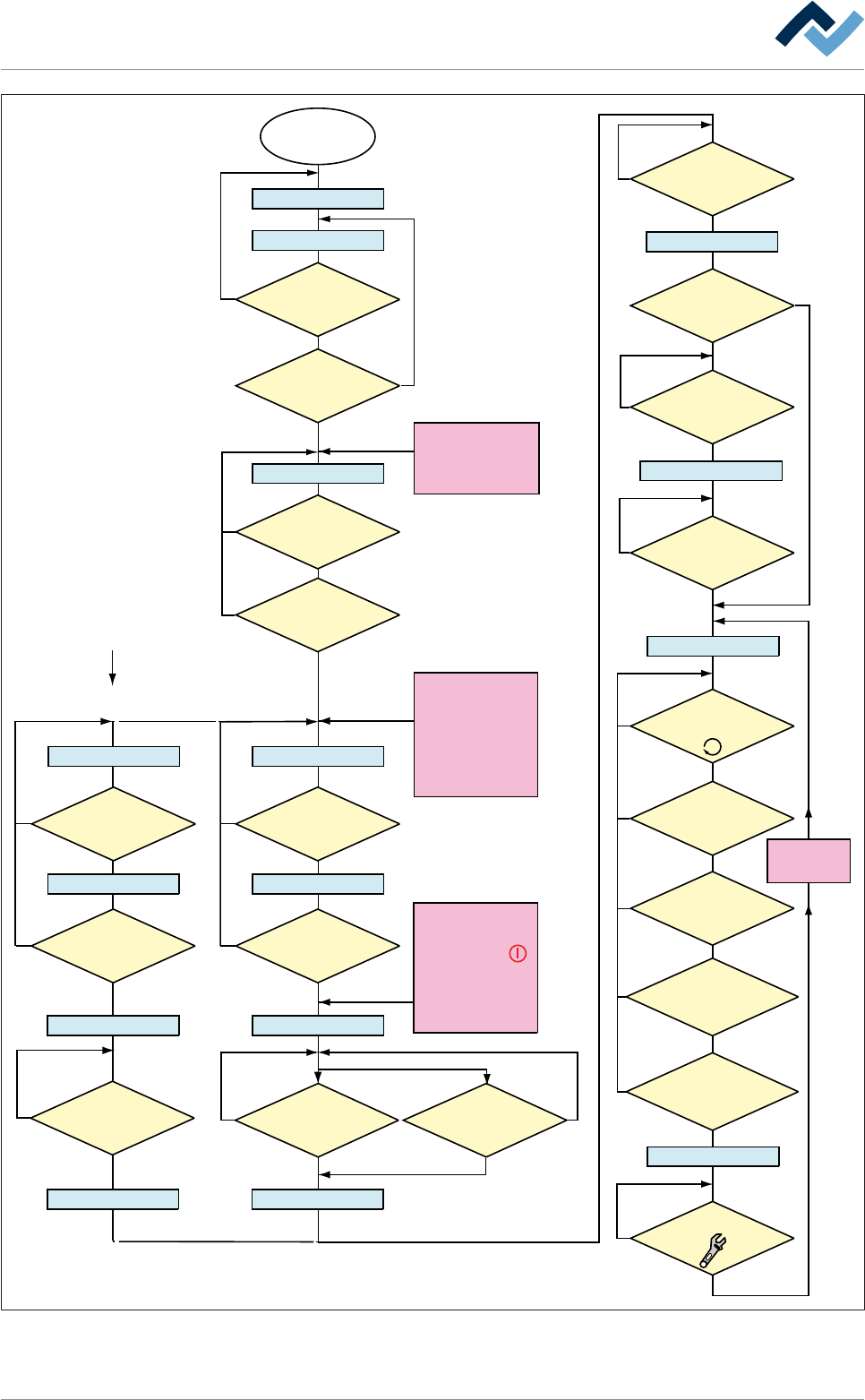
6|Function description
Within the Option
[blue RESET button]
Main switch
ON
Electronic OFF
Electronic Init
Power OFF
Voltage supply OKVoltage supply OK
Check emergency-stopCheck emergency-stop
Movement OFF Movement OFF
Maintenance mode
Button
[Movement ON] pressed?
No
NoNo
No
No
No
Yes
Yes
Yes
Referencing off all
servo axes OK?
No PCB inside the
machine?
No
Yes
NO message is
pending which prevents the
change to [Automatic]
No
Yes
Has the operator
selected a soldering program?
No
Yes
Yes
No
Yes
Yes
Yes
Has a pre-activate
point been reached, e.g.
[Heating]?
No
Yes
Weekly timer
in ON phase?
Has the blue
RESET button been
pressed?
No
Yes
Yes
Emergency-off OK?
No
Emergency-off OK?
No
Yes
Exhaust air OK?
The following condition also
directly results in
[Voltage supply OK]:
- Emergency-off pushed
OR emergency-off
error
- Weekly timer in OFF
phase AND machine
empty
No error for
[Electronic OFF]
pending?
CAN initializ
ing AND PLC
initializing OK?
Button [Automatic]
pressed?
No
No
Movement ON
Button
[Movement ON] pressed?
No
Yes
Movement ON
Machine Init
Referencing servo axes
Internal: PLC OK?
Referencing
Servo axes OK?
No
Yes
Yes
Yes
No
Yes
Has the
operator started the
referencing of the Servo
axes?
No
Are servo axes
availabe?
No
Supply
voltage OK?
Button
[Maintenance] pressed?
The following condition also
directly results in [Power Off]:
- The
visualization
software version is
outdated.
The following condition also
directly results in
[Movement OFF]:
- The [Movement Off]
key has been pushed
- An error is pending which
results in [Movement off];
e.g. optional CAN device
not configured
The dialog
[...................]
is displayed
Automatic
Flussdiagramm: Die blauen Rechtecke definieren die Betriebsarten der Maschine. Diese Betriebsarten
werden auch in der Statusleiste der Bedienoberfläche angezeigt.
Ersa GmbH Operating Instructions_VF335_en|Rev. 14|30/11/2017 219/695