Operating Instructions_VF335_en.pdf - 第396页
8|Service and maintenance Cleaning the solder surface 4 5 5 6 7 1 2 Fig.146: Cleaning the solder surface ü To clean the solder surface: a) Remove dross from the entire solder surface (1) using a solder scraper (2) or …
8|Service and maintenance
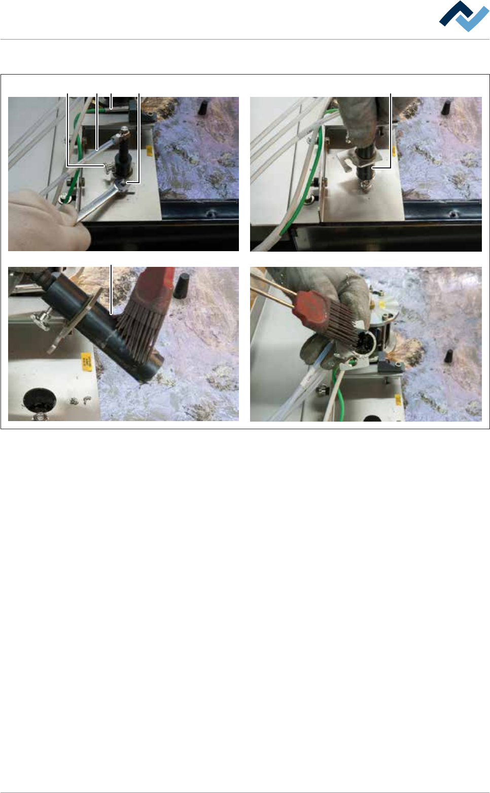
Cleaning the solder level monitoring
2
5
1
3
4 5
Fig.145: Cleaning the solder level monitoring
ü To clean the solder level monitoring:
ü Note: The parts coming into contact with solder are easier to clean while they
are still hot!
a) Perform a visual inspection of the thermocouple (1).
ð The connection line must not be porous or hardened.
b) Have the damaged thermocouple replaced by specialist staff.
c) Performing a visual inspection of the hose (3). Tightness and firm fit must be
guaranteed. Have qualified staff replace any heavily discoloured, porous or
hardened hose.
d) Loosen the nut (4).
e) Note: Do not loosen the knurled screw (2)!
f) Turn the probe unit (5) clockwise, pull it out upwards, and clean inside and out-
side.
ð In the rising pipe of the probe unit there is a bore.
g) Clean the bore - it must be clean and free of dirt.
h) Reinstall the solder level monitoring.
ð The process has now been completed.
Ersa GmbH Operating Instructions_VF335_en|Rev. 14|30/11/2017 395/695
8|Service and maintenance
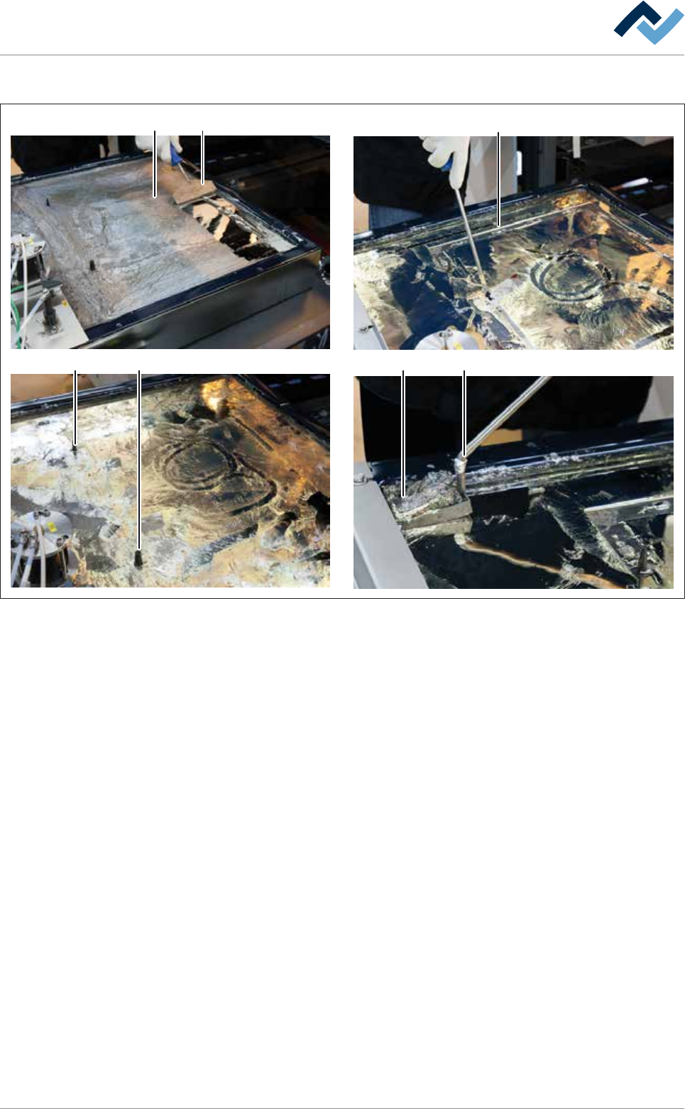
Cleaning the solder surface
4
5 5
67
1
2
Fig.146: Cleaning the solder surface
ü To clean the solder surface:
a) Remove dross from the entire solder surface (1) using a solder scraper (2) or a
silicone scraper.
b) Collect the dross in a corner of the solder pot.
ð Note: Work carefully exerting little pressure so as not to damage the
coated surfaces!
c) Carefully clean the area around the encoding pins (5).
d) Carefully clean the contact points of the encoding pins and pressure chamber.
ð Note: This cleaning process is particularly important. The area around the
contact points must be free of oxides and dross. After installing the nozzle
plate, adhering dirt can lead to leaks!
e) Remove the dross (7) with a perforated ladle (6).
f) If necessary, refill some solder so as to obtain the original solder level again.
ð The process has now been completed.
Ersa GmbH Operating Instructions_VF335_en|Rev. 14|30/11/2017 396/695
8|Service and maintenance
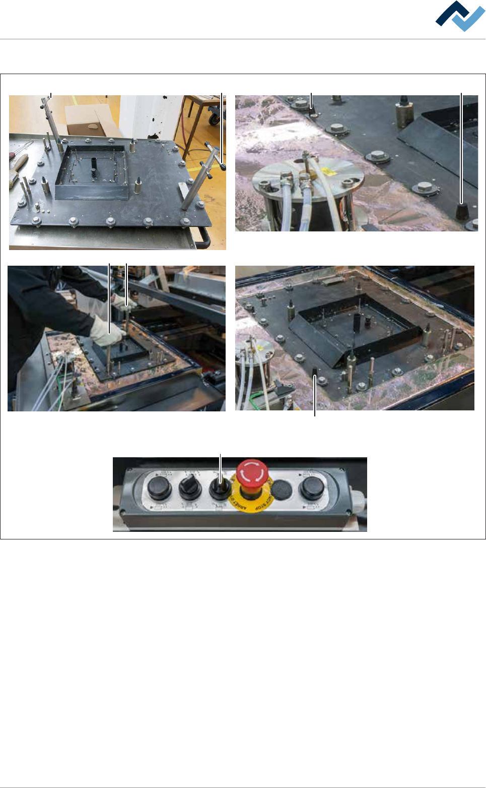
Assembling the nozzle plate
A A X
1
2
3
4
5
11
6
7
8
9
10
12
13
14
15
16
17
18
1
X
B
C
B
D
Fig.147: Assemble the nozzle plate. Always grasp locked extraction tools by the top handle (A)!
ü To assemble the nozzle plate:
ü Both extraction tools are fitted and secured to the nozzle plate.
ü The upper edge of the pressure chamber is completely covered with solder and
free of oxides and dross.
ü All bayonet locks are aligned in such a way that the slots of the screws run par-
allel to the edges of the nozzle plate.
a) Accident risk! Check the firm seating of the locks again!
b) Lift the nozzle plate with both hands by the top handles (A) .
ð Accident risk! Always grasp locked extraction tools by the top handle (A)!
c) Place the nozzle plate very slowly onto the solder surface and position it gently
via the coding keys (X).
ð If the machine has the [setup verification] option:
d) Insert the RFID chips in the chip reader.
Ersa GmbH Operating Instructions_VF335_en|Rev. 14|30/11/2017 397/695