Operating Instructions_VF335_en.pdf - 第193页
6|Function description NOTE Using the area spray head If you are working with the area spray head, the document [268447] is available. The document can be found in the data carrier [product_data_selective], which is in…
6|Function description
ü To assign the reference point to another nozzle:
a) Deactivate the [Fluxer coordinates relate to nozzle 1] checkbox.
ð This action always assigns the reference point to the nozzle with the lowest
number according to the mode. Example: If mode [6] has been selected, the
reference point is assigned to the nozzle with the lowest number according to
mode 6, i.e. nozzle 2. If values are entered into the [Endposition X] / [Endposi-
tion Y] registers, nozzle 2 is always moved to this and position. Nozzle 2 is al-
ways the reference point.
ü Entering the spraying quantity:
a) Enter the [%] amount of flux to be sprayed into the [Spray amount [%]] re-
gister.
ð If a value is entered here, the corresponding amount of flux material will be
sprayed. If no value is entered here, no flux will be sprayed. The spray head is
only positioned.
ü Entering the spray time, spot and path spraying:
a) Enter the spray time into the [Spray time [s]] register.
ð If a value is entered here, the spray head is moved to position X/Y and, for
the [Spray time [s]] time, a spot is sprayed.
ð If no value is entered here, the spray head is approached to position X/Y.
During the travel movement, a path is sprayed with the [Spray amount
[%]].
ð The process has now been completed.
Further application examples:
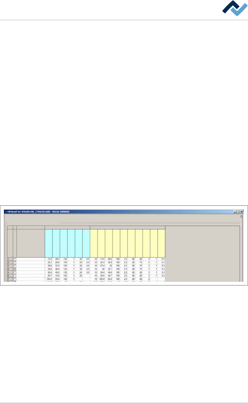
Soldering program editor
Set data
Set data
Flux unit Soldering unit 1
Set
Hide
Description
Endposition X [mm]
Endposition Y [mm]
Speed X/Y [mm/s]
mode
Spray amount [%]
Spray time [s]
Z while moving [mm]
Endposition X [mm]
Endposition Y [mm]
Speed X/Y [mm/s]
Endposition Z [mm]
Speed Z [mm/s]
Wave height [%]
Soldering time [s]
Lower value [%]
Lowering time [s]
– Set number 1: Position [X = 13.5] / [Y = 29.5] is approached with [Nozzle 1] at a
speed of [130 mm/s]. The nozzle sprays a spot with a [30%] dosage for the
time of [0.5 s].
– Set number 2: Position [X = 25.3] / [Y = 29.8] is approached with [Nozzle 2] at a
speed of [130 mm/s]. The nozzle sprays a spot with a [30%] dosage for the
time of [0.5 s].
– Set number 4: This data set is hidden (the [Hide] checkbox is enabled). The
data set is therefore not processed.
– Set number 7: Position [X = 104.5] / [Y = 54.2] is approached with [Nozzle 1] at
a speed of [130 mm/s]. The nozzle remains there without spraying.
– Set number 8: The position [X = 104.6] / [Y = 65.9] is approached with [Nozzle
1] at a speed of [15 mm/s]; in the process, it sprays a path with a [30%] dosage.
This behaviour only occurs when the [Fluxer coordinates relate to nozzle 1] check-
box has not been enabled in the [Soldering program editor Set data] dialog.
Ersa GmbH Operating Instructions_VF335_en|Rev. 14|30/11/2017 192/695

6|Function description
NOTE
Using the area spray head
If you are working with the area spray head, the document [268447] is available. The
document can be found in the data carrier [product_data_selective], which is included
in the delivery scope.
Ersa GmbH Operating Instructions_VF335_en|Rev. 14|30/11/2017 193/695
6|Function description
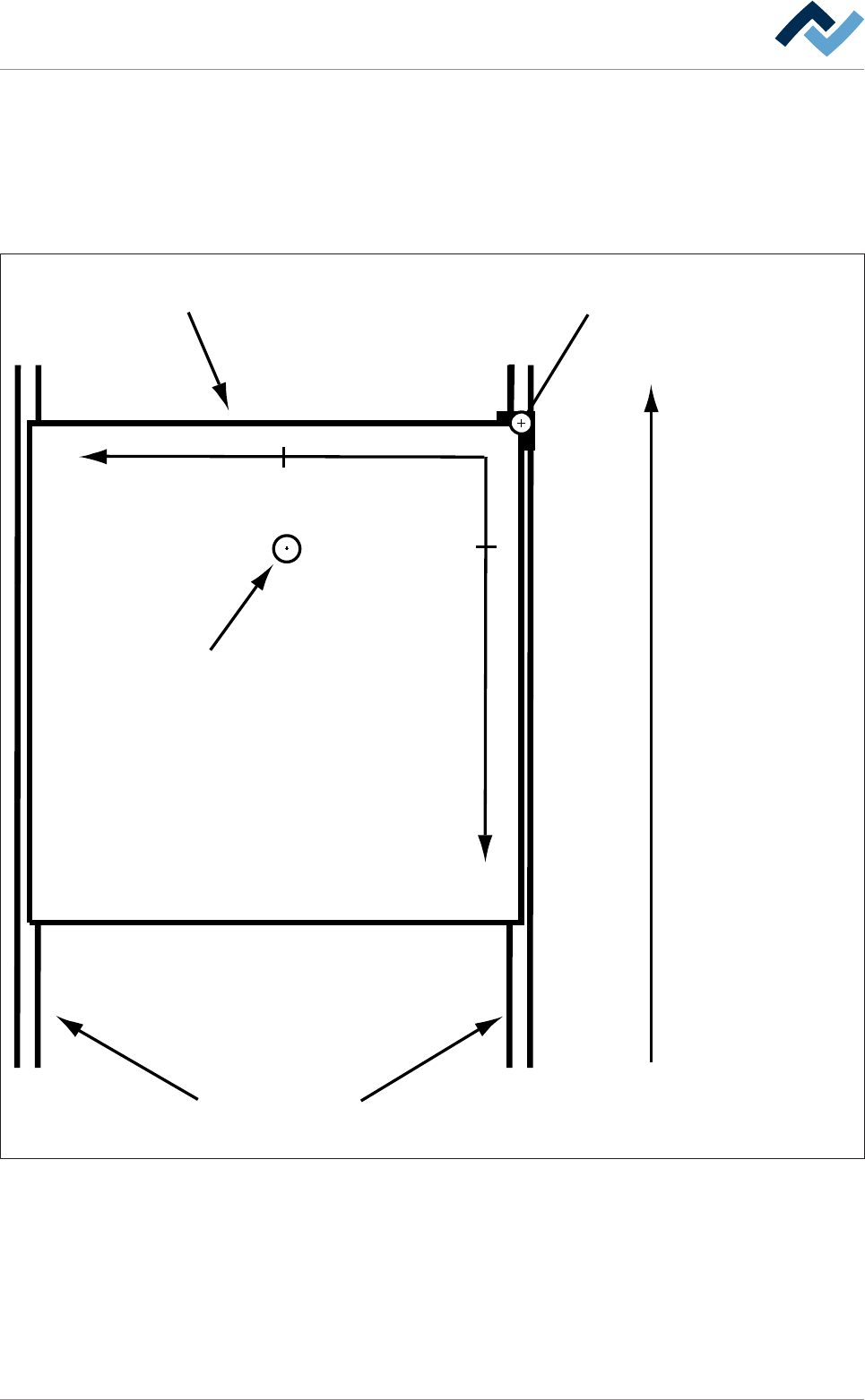
6.9.12.2 Soldering module data set (single pot)
You can enter the nozzle target positions in the form of coordinates in the re-
gisters. If you enter coordinates, these are always considered target coordinates
starting from the barrier (= point of origin). You can enter the coordinates in [mm]
with an accuracy of 1/10mm via the keyboard. Please also consider the following
drawing:
Transfer direction
Blocker (= zero-point)Board
Conveyor
+Y
+X
29,5
13,5
Tip
Fig.44: Entering soldering coordinates: In the example above, the nozzle is located at the end position [X = 13.5] / [Y = 29.5] (view
from above).
Ersa GmbH Operating Instructions_VF335_en|Rev. 14|30/11/2017 194/695