Operating Instructions_VF335_en.pdf - 第79页
4|Transport, installation, storage, disposal 1 2 Fig.15: Alignment in a longitudinal direction Tighten counter nuts ü After aligning: a) tighten all counter nuts on the adjustable feet with an open-end wrench. ð The p…
4|Transport, installation, storage, disposal
4.9.4 Aligning the machine
It might be necessary to carry out the alignment of the machine several times.
After an alignment, check the steps that were carried out before and if necessary
adjust the concerned adjustable feet. Continue to align the machine until you have
reached an acceptable result.
ü Roughly aligning the machine with the adjustable feet:
a) Required tools: Precision spirit level, steel rule, open-end wrench.
b) Screw all adjustment feet to the same height with the open-end wrench. In this
case, respect the required infeed and outfeed height.
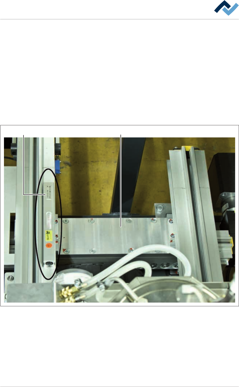
ü Aligning in a transverse direction:
a) Place the precision spirit level (1) in a transverse direction on the soldering
module (2).
b) Align the machine with the adjustable feet using an open-end wrench.
1 2
Fig.14: Aligning in a transverse direction:
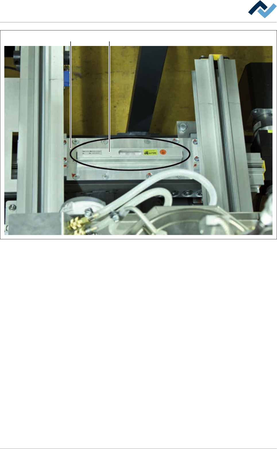
ü Aligning in a longitudinal direction:
a) Place precision spirit level (1) in a longitudinal direction on soldering module
(2)
b) Align the machine with the adjustment feet using an open-end wrench.
Ersa GmbH Operating Instructions_VF335_en|Rev. 14|30/11/2017 78/695
4|Transport, installation, storage, disposal
1
2
Fig.15: Alignment in a longitudinal direction
Tighten counter nuts
ü After aligning:
a) tighten all counter nuts on the adjustable feet with an open-end wrench.
ð The process has now been completed.
4.9.5 Remove the unit transport locks
The following units were secured prior to transport:
– Soldering units
– Fluxer unit
– Preheaters
– Flux material tank
ü Remove all transport locks:
a) Use a suitable tool.
b) Keep the transport locks for later use!
4.10 Assembling components
As a rule, the machine is supplied as a unit, except for the signal lamp. In individual
cases, e.g. due to local conditions, the machine is delivered in modules.
Ersa GmbH Operating Instructions_VF335_en|Rev. 14|30/11/2017 79/695
4|Transport, installation, storage, disposal
CAUTION
Possible machine malfunctioning! Possible personal and material damage!
a) Modules must be assembled by trained and qualified staff only.
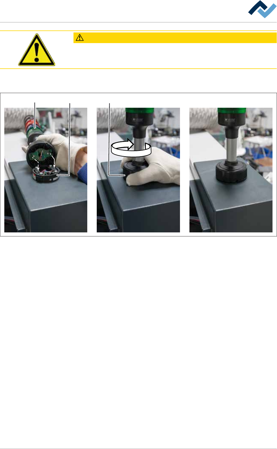
4.10.1 Assembling the signal lamp
A
B
B
A
1 2 3
ü Assembling the signal lamp:
a) Position the indicator light (1) so that the pins (A) are flush with the bushings
(B).
b) Insert the indicator light on the base (2) and turn the union nut (3) clockwise
until it stops.
ð The process has now been completed.
4.10.2 Assembling the code reader
ü Assembling and connecting the code reader:
a) use a suitable tool.
b) The electrical connection is to be carried out by trained and qualified electri-
cians.
c) Read the wiring diagrams provided.
d) Connect the code reader to the interface provided.
ð The process has now been completed.
4.11 Connecting the machine
This section describes the electrical connection as well as the connection to the
supply and disposal systems. The work described may only be performed by trained
and qualified staff and/or skilled specialists.
Ersa GmbH Operating Instructions_VF335_en|Rev. 14|30/11/2017 80/695