Operating Instructions_VF335_en.pdf - 第250页
6|Function description The offset value has also the largest control power portion for the solder pump. The remaining portion of control power is derived from the product of wave power and gradient. The Gradient determ…
6|Function description
The power control results from Wave power, Gradient and Offset!
Gradient
Offset
Wave power
30000
Control
Pump
Pump
Control
Soldering nozzle
Soldering nozzle
(B)
(A)
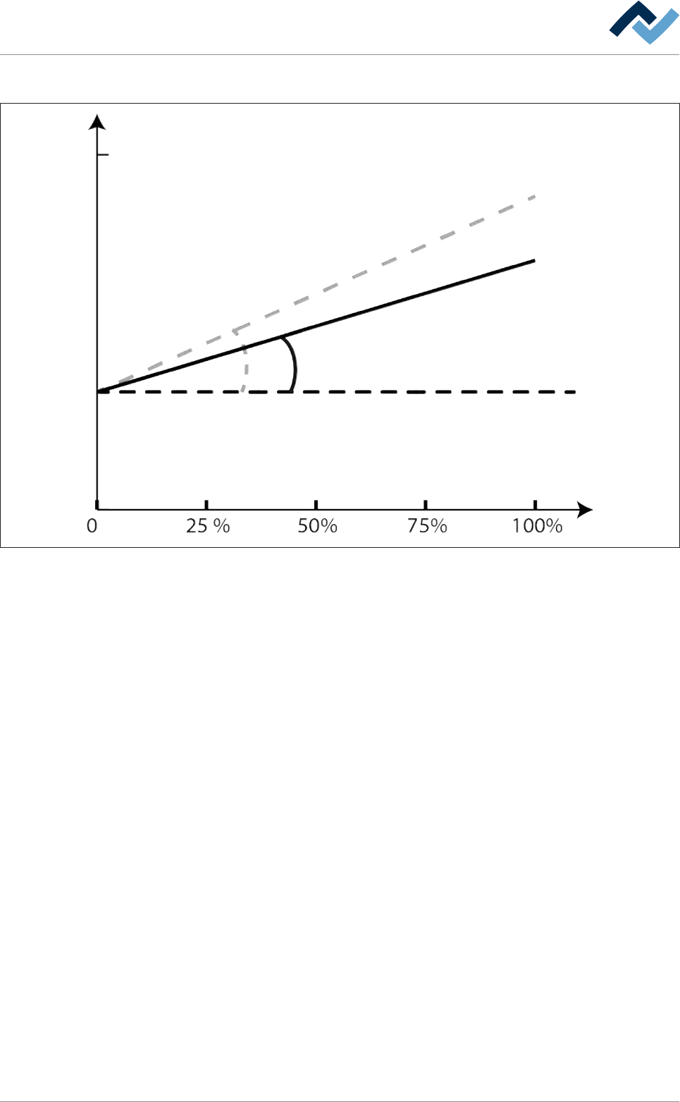
Fig.65: Pump power control: The relationship between Wave power, Gradient and Offset.
For an optimal soldering result, different nozzles must be also operated with different con-
trol power. The black characteristic curve shows the course of the control power for nozzle
(A); the grey curve shows the course of the control power for nozzle (B).
The relationship between Wave power, Gradient and Offset can be graphically illus-
trated as shown here. Offset is the value that is required to leave the solder lying
about 4 mm below the nozzle edge with a wave power of 1%. In this case, the con-
trol power is purely a numerical value can be calculated with the following formula:
Control power = Offset + (Wave power * Gradient)
Ersa GmbH Operating Instructions_VF335_en|Rev. 14|30/11/2017 249/695

6|Function description
The offset value has also the largest control power portion for the solder pump.
The remaining portion of control power is derived from the product of wave power
and gradient.
The Gradient determines by how much the control power increases with a minimal
change in the Wave power.
Note: For different nozzles, also different gradients must be determined. The result
is that, for different nozzles, there are other control power curves!
Ersa GmbH Operating Instructions_VF335_en|Rev. 14|30/11/2017 250/695
6|Function description
6.15.2 The [Solder nozzle data table] settings dialog
Data table solder nozzle
Active nozzle
Name
nozzle number
Description
X [mm]
Y [mm]
Dimension Y [mm]
Dimension Z [mm]
Offset test...
Offset test...
Y [mm]
X [mm]
Test distance [mm]
Gradient
Offset cold
Test tolerance minus
Offset warm
Test tolerance plus
Test offset max.
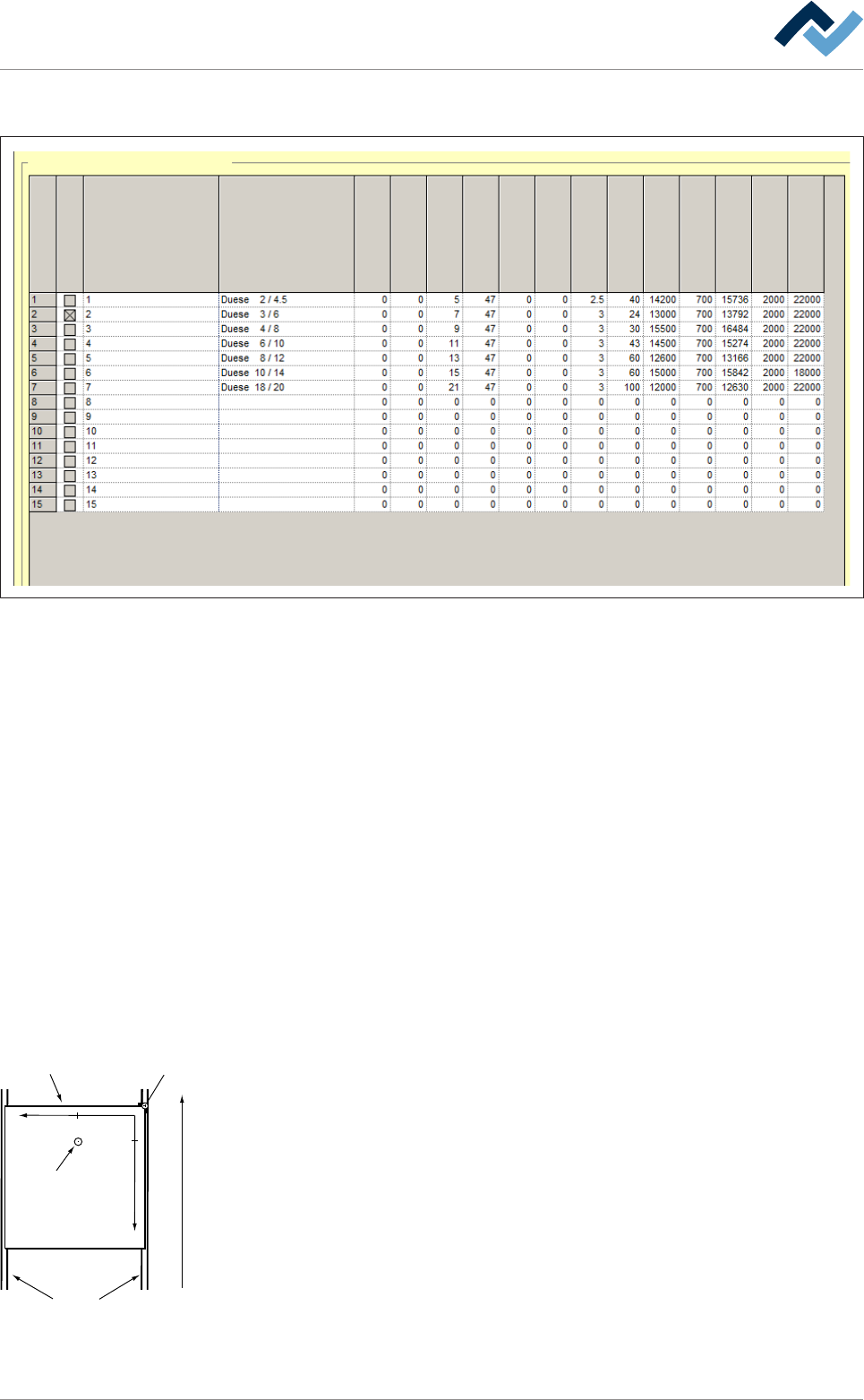
Fig.66: The settings dialog [Data table solder nozzle]
The Data table solder nozzle is used to manage the solder nozzles required for pro-
duction. You can save and examine the settings for up to 15 different solder
nozzles.
The nozzle table contains the following values:
– [nozzle number]: Sequential numbering of the nozzles.
– [Active nozzle]: If this checkbox is activated, stored settings are used for this
nozzle. You can always activate only one nozzle.
– [Name]: Here you can enter a nozzle name.
– [Description]: Here you can enter a description of the nozzle; it would make
sense, for example, to enter the nozzle inner and outer diameters and the
height.
– [X [mm]] and [Y [mm]]: These values are used to determine the centre of the
nozzle. The values must be entered only for nozzles that have no rotationally
symmetrical shape. [X [mm]] and [Y [mm]] indicate how many millimetres the
centre of the nozzle is away from the centre of the nozzle base in the X/Y direc-
tion.
Transfer direction
Blocker (= zero-point)Board
Conveyor
+Y
+X
29,5
13,5
Tip
– [Dimension Y [mm]]: Here, the outer diameter of the nozzle is indicated in milli-
metres plus an addition of 1 mm. This value is used to calculate the software
limit switch to prevent the nozzle from colliding with the conveyor rail. With
regrd to this, please observe the following illustration. A sample calculation for
a nozzle having an outer diameter of 8 mm: Dimension Y [mm] = Outer dia-
meter [mm] + addition [1 mm] Dimension Y [mm] = 8 + 1 = 9 [mm]
– [Dimension Z [mm]]: Here, the height of the nozzle is specified in millimetres.
– [Offset test X[mm]] and [Offset test Y[mm]]: These values are used to determ-
ine how much the desired test position of the solder wave height test should
deviate from the centre of the nozzle base. Here, an input is only required
when no nozzle is located at the centre of the nozzle base; this is the case, for
example, when a Min-Dip nozzle is used.
Ersa GmbH Operating Instructions_VF335_en|Rev. 14|30/11/2017 251/695