Operating Instructions_VF335_en.pdf - 第435页
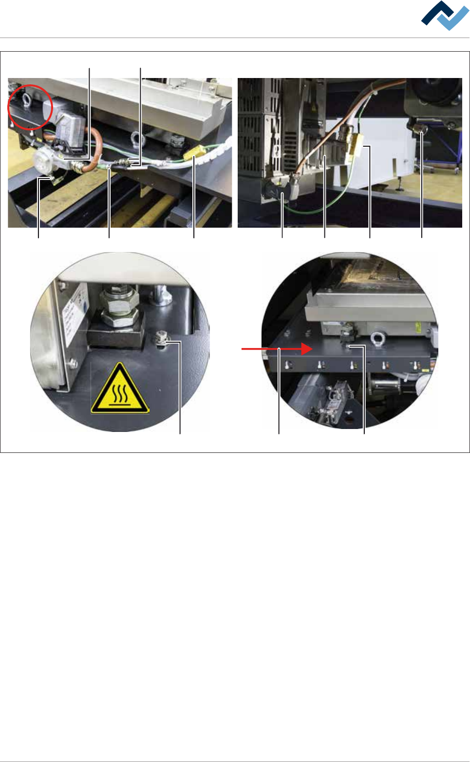
8|Service and maintenance 17 16 18 19 21 22 23 24 25 25 26 20 Fig.172: Connect all quick-acting couplings and plug-in connectors h) Lift the holder of the cable carrier (26) from the machine over the DIP solder pot, b…
8|Service and maintenance
10 9
10 1112 13
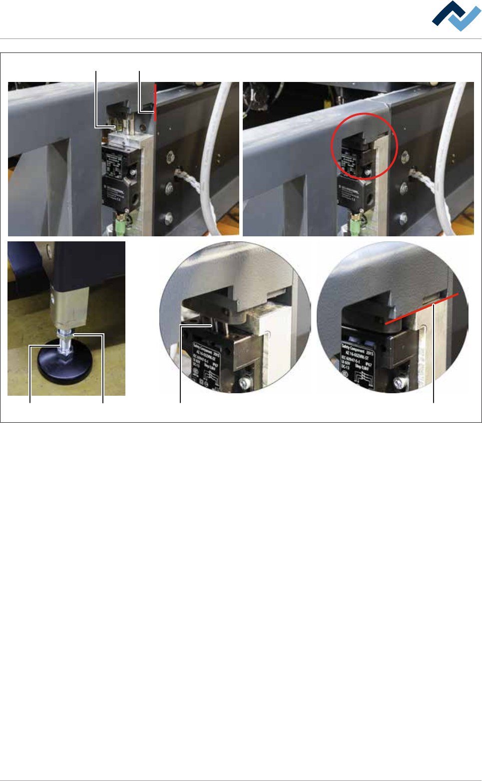
Fig.171: Lowering the replacement rack and inserting the switching cams
g) Using the lifting cart, carefully lower the replacement rack until its guide rails
are placed level on both locating surfaces of the machine (11).
ð At this point, the adjustable feet (12) of the replacement rack must be on
the floor.
ð While the equipment is lowered, the switching cams (10) must slide into
the switch and must not be canted.
Ersa GmbH Operating Instructions_VF335_en|Rev. 14|30/11/2017 434/695
8|Service and maintenance
17 16
18 19 21 22 23 24
25 2526
20
Fig.172: Connect all quick-acting couplings and plug-in connectors
h) Lift the holder of the cable carrier (26) from the machine over the DIP solder
pot, bring it to the required position and push it to the right on the replace-
ment rack.
ð The screwed connections (25) must slide completely into the guides of the
holder of the cable carrier.
i) Tighten both screws (25) of the holder of the cable carrier on the front and on
the rear of the DIP solder pot.
j) Loosen and remove the fixing bar of the DIP solder pot on the replacement
rack.
k) Connect both quick-acting couplings (16) and all eight plug-in connectors
(17-24).
Ersa GmbH Operating Instructions_VF335_en|Rev. 14|30/11/2017 435/695
8|Service and maintenance
1514 14 14
9
27
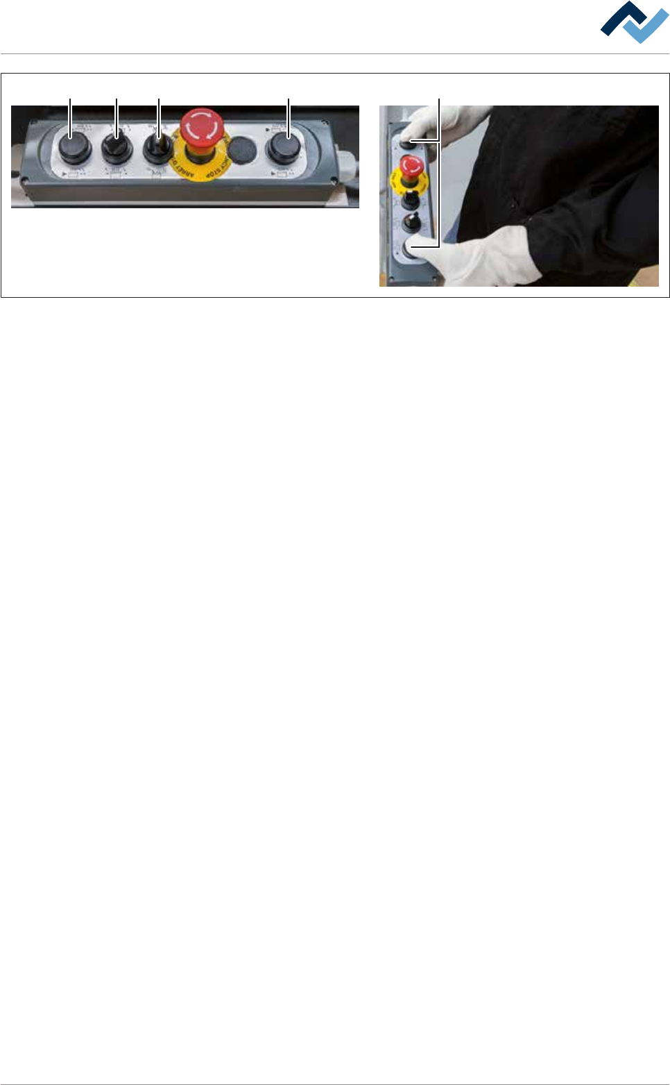
Fig.173: Driving the DIP solder pot into the unit
l) On the control console, rotate switch (15) in the position shown.
m)Press and hold both buttons at the same time (14).
ð The solder pot is now conveyed into the machine and will automatically
stop in its final position.
n) Release the buttons (14).
o) Quickly activate the switch (27) to reset.
p) Close the cover of the gassing hood.
q) Using the lifting cart, lift the replacement rack until the height (2) is at least 15
mm greater than the height (1) of the DIP soldering module guide rail.
r) Carefully pull the lifting cart away from the machine.
s) Remove the traction aid from the machine.
t) If the machine has the [Hold Down] option, remove the [Hold Down].
u) If the machine has the [Solderbar feeder] option, remove the [Solderbar
feeder] from the storage compartment of the corresponding DIP solder pot
and insert theSolderbar feeder] back into the appropriate holder.
v) Close all the doors of the machine.
ð The process has now been completed.
Ersa GmbH Operating Instructions_VF335_en|Rev. 14|30/11/2017 436/695