Operating Instructions_VF335_en.pdf - 第467页
9|Spare and wear parts 9.3.5 Spray monitoring (optional) Spray monitoring 3 3 3 3 2 4 1 Fig.195: EM122-45-00_EM113-45-00 Pos Description Item number A B 1 Laser sensor 23643 x 2 Spring steel clamp 6FEDKL-G-D6-Z x 3 Pr…
9|Spare and wear parts
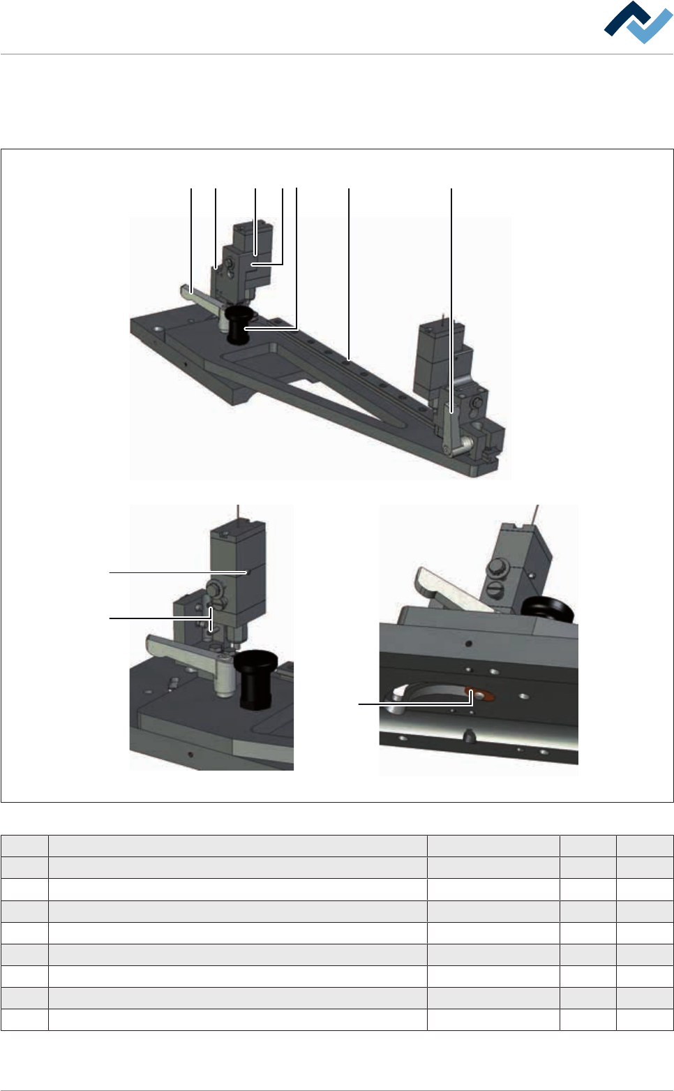
9.3.4 Accommodating the adjustable spray head
1
2
45 73 6
6
7
5
Fig.194: EM113-41-02-00
Pos Description Item number A B
1 Spray head holder, adjustable 172048 x
2 Groove block 172063 x
3 Spray head holder, adjustable 145269 x
4 Guide rail with slider 184463 x
5 Set screw M03X003 zinc-plated ISO 4026/DIN 913 6M03X003Z0913 x
6 Catch bolt 74763 x
7 Adjustable clamping lever 171954 x
8 Set screw 6M03X010Z0914 x
Ersa GmbH Operating Instructions_VF335_en|Rev. 14|30/11/2017 466/695
9|Spare and wear parts
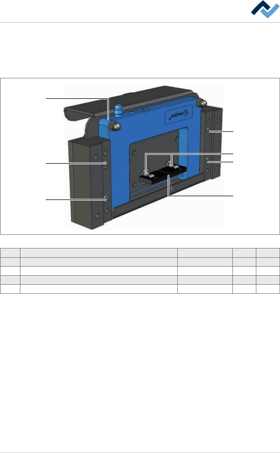
9.3.5 Spray monitoring (optional)
Spray monitoring
3
3
3
3
2
4
1
Fig.195: EM122-45-00_EM113-45-00
Pos Description Item number A B
1 Laser sensor 23643 x
2 Spring steel clamp 6FEDKL-G-D6-Z x
3 Pressure piece M8 114126 x
4 Evaporator 231417 x
Ersa GmbH Operating Instructions_VF335_en|Rev. 14|30/11/2017 467/695
9|Spare and wear parts
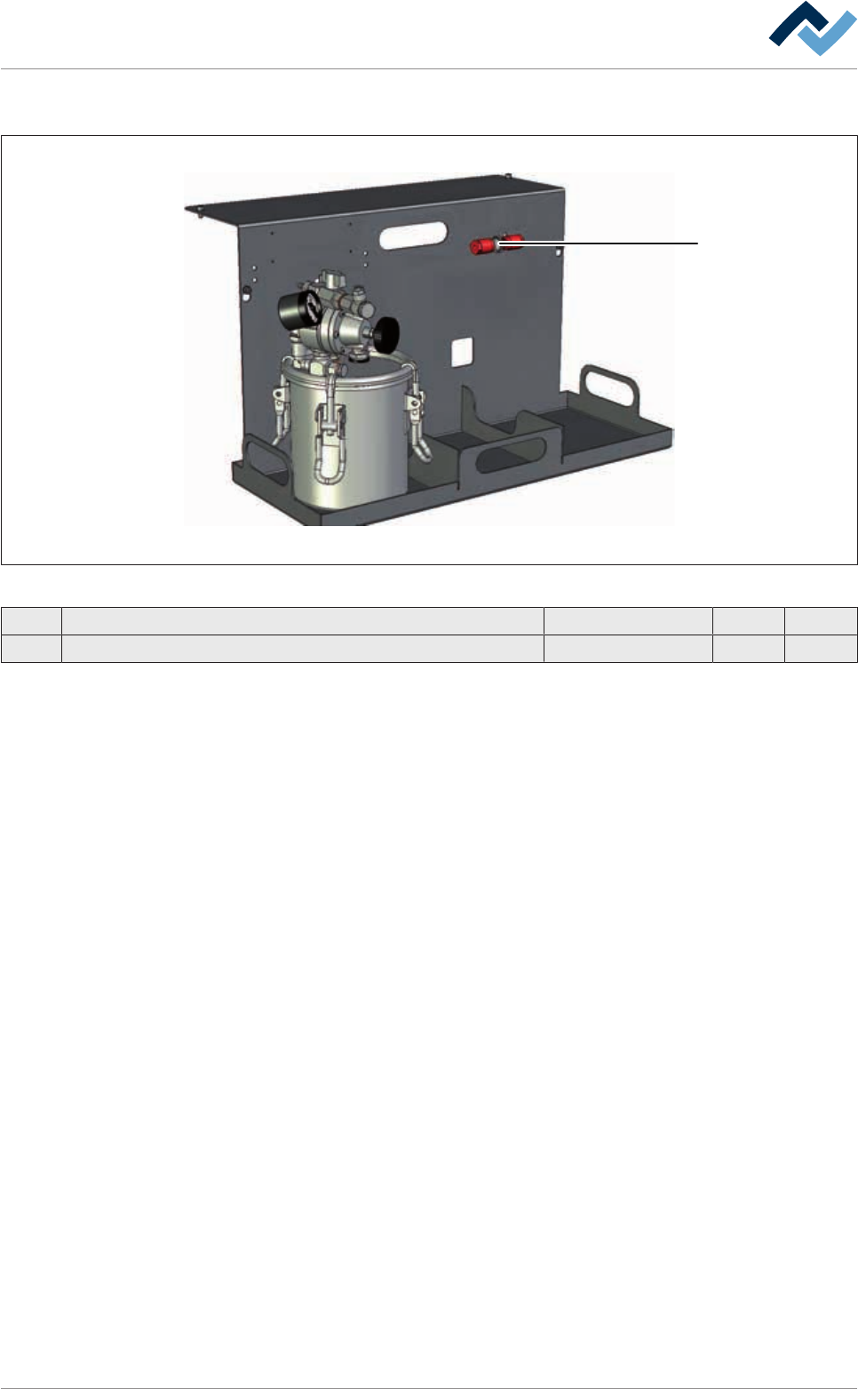
9.3.6 Flux material stockage
1
Fig.196: EM113-43-00
Pos Description Item number A B
1 Filter with bolting 203147 x
Ersa GmbH Operating Instructions_VF335_en|Rev. 14|30/11/2017 468/695