Operating Instructions_VF335_en.pdf - 第613页
9|Spare and wear parts Pos. Description Part No. A B 1 Closure 6SPV-TL806B x 2 Graphite sealing ring 192323 x 3 Lock screw L2C 153855 x 4 Electro magnetical pump, type B02 (standard) 145982 x Electro magnetical pump, t…
9|Spare and wear parts
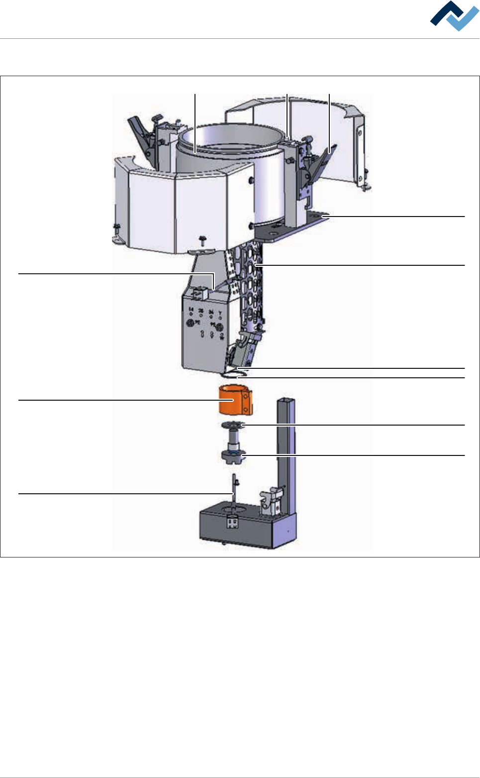
9.8.5 Solder pot, asymmetrical (single track)
1108
7
2
6
5
9
3
4
6
9
Fig.328: EM122-62-00, EM122-61-00
Ersa GmbH Operating Instructions_VF335_en|Rev. 14|30/11/2017 612/695

9|Spare and wear parts
Pos. Description Part No. A B
1 Closure 6SPV-TL806B x
2 Graphite sealing ring 192323 x
3 Lock screw L2C 153855 x
4 Electro magnetical pump, type B02 (standard) 145982 x
Electro magnetical pump, type D01 (option) 266106 x
5 Pump centering ring 153876 x
6 Thermocouple 2xNICR-NI D3 with plug 154236 x
7 Ring heater (pump tube) 150 W --> 02/2015 6HKRI36H36 x
7 Heating element, pump sump, 230 V / 150 W 03/2015 -->
10/2017
273536 x
7 Heating element, pump sump, 230 V / 150 W 10/2017 --> 312371 x
8 Ring heater (pot) 1000 W 153896 x
9 Locking ring 109650 x
10 Cylindrical pin 219468 x
Ersa GmbH Operating Instructions_VF335_en|Rev. 14|30/11/2017 613/695
9|Spare and wear parts
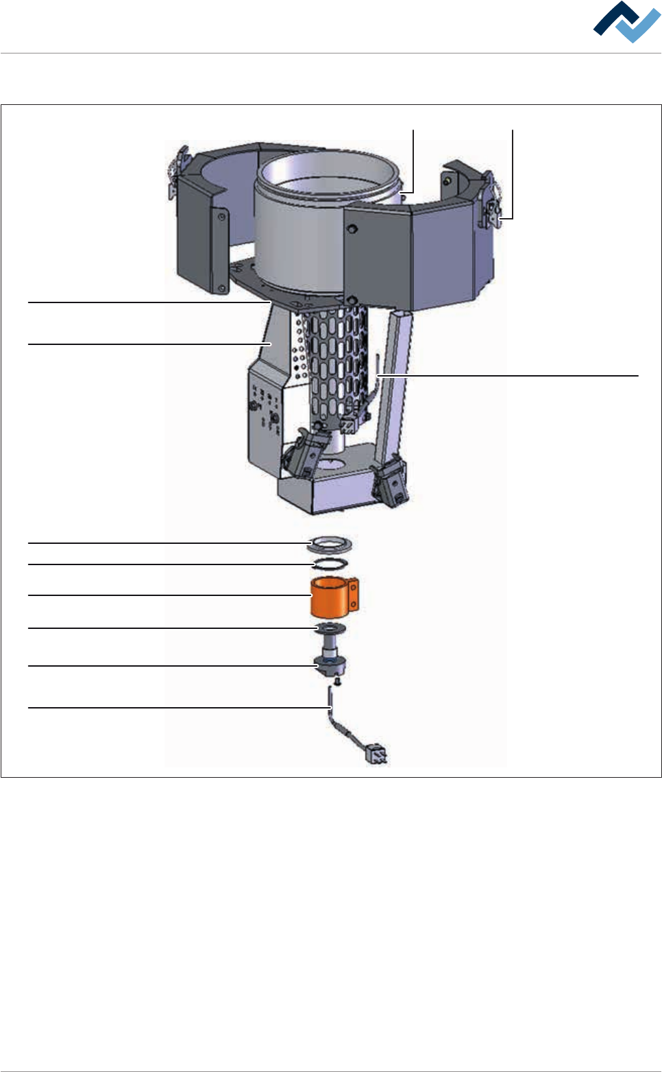
9.8.6 Solder pot, symmetrical, dual track
8
2
3
4
9
5
9
7
6
6
1
Fig.329: EM113-60-00, EM113-69-00
Ersa GmbH Operating Instructions_VF335_en|Rev. 14|30/11/2017 614/695