Operating Instructions_VF335_en.pdf - 第275页
6|Function description Configure the settings for the solder feed ü Enter the settings: ü The machine is in the operating mode [Maintenance mode] function. ü A user logging into the system has respective rights. a) Pre…
6|Function description
1 2
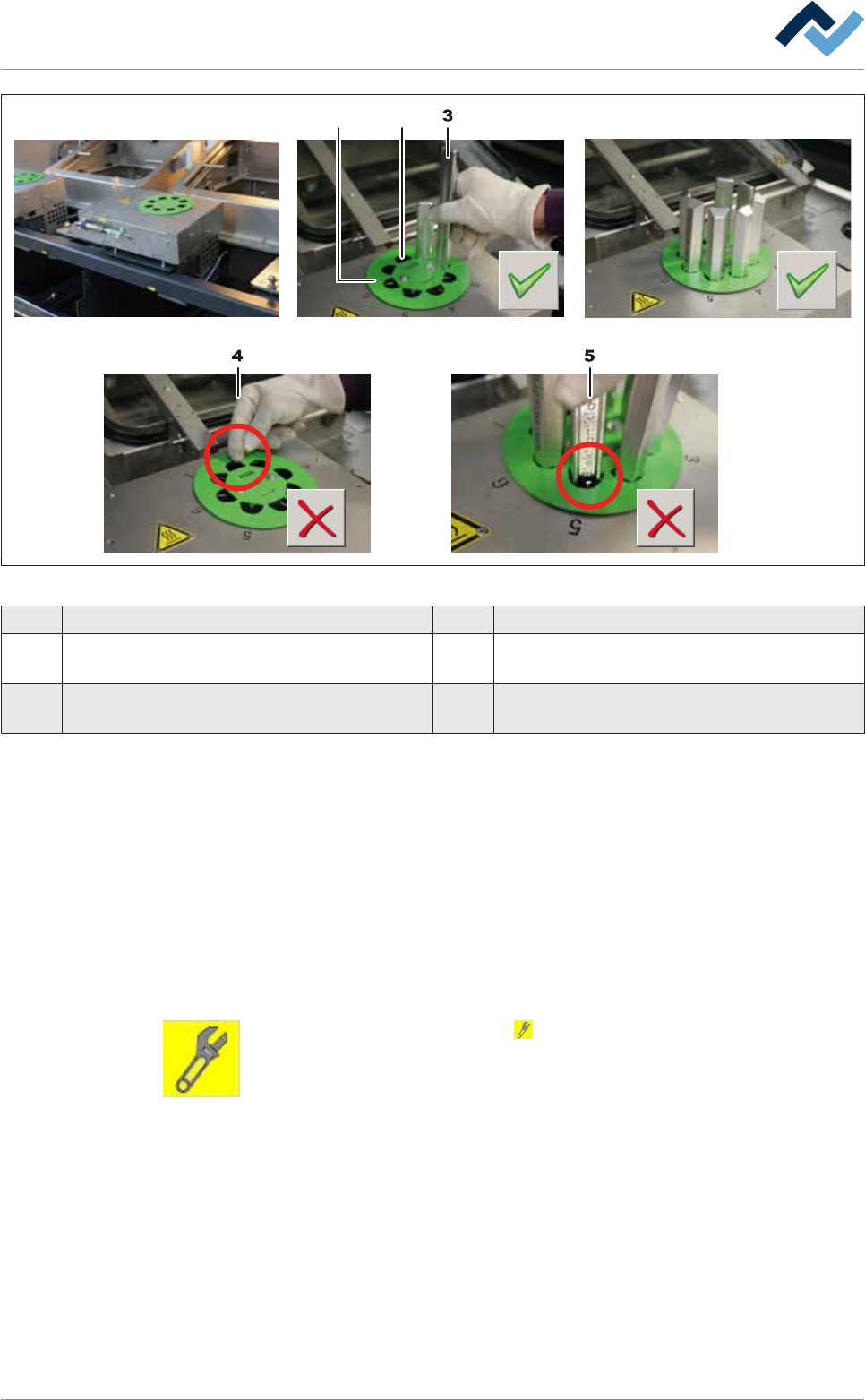
Fig.77: Fill the turret bar container
1 Coding disk 2 Discharge duct
3 Solder bar 4 Wrong: Do not insert solder bars in the discharge
duct!
5 Wrong: Insert exclusively suitable solder bars
into the container!
a) Unpack the solder bars. Check the labels on every packaging. Do not mix up dif-
ferent solders!
ð If a coding disk (1) is mounted:
b) Make sure that the solder bars (3) fit perfectly in the recesses.
c) Insert a total of 7 solder bars into the container.
d) Note: Do not insert any solder bars into the discharge duct (2)! The bar would
fall immediately into the solder pot!
ð After filling the container:
e) Close the hood of the machine.
f) In the [Switch functions] frame press the button to deactivate module main-
tenance. When this mode is completed, the button turns grey.
g) Open the [Messages] input dialog and acknowledge all existing messages.
ð The process has now been completed.
Ersa GmbH Operating Instructions_VF335_en|Rev. 14|30/11/2017 274/695

6|Function description
Configure the settings for the solder feed
ü Enter the settings:
ü The machine is in the operating mode [Maintenance mode] function.
ü A user logging into the system has respective rights.
a) Press the soldering module icon in the start dialog.
ð The [Soldering module] window appears.
b) Click on the button in the lower toolbar.
Ersa GmbH Operating Instructions_VF335_en|Rev. 14|30/11/2017 275/695
6|Function description
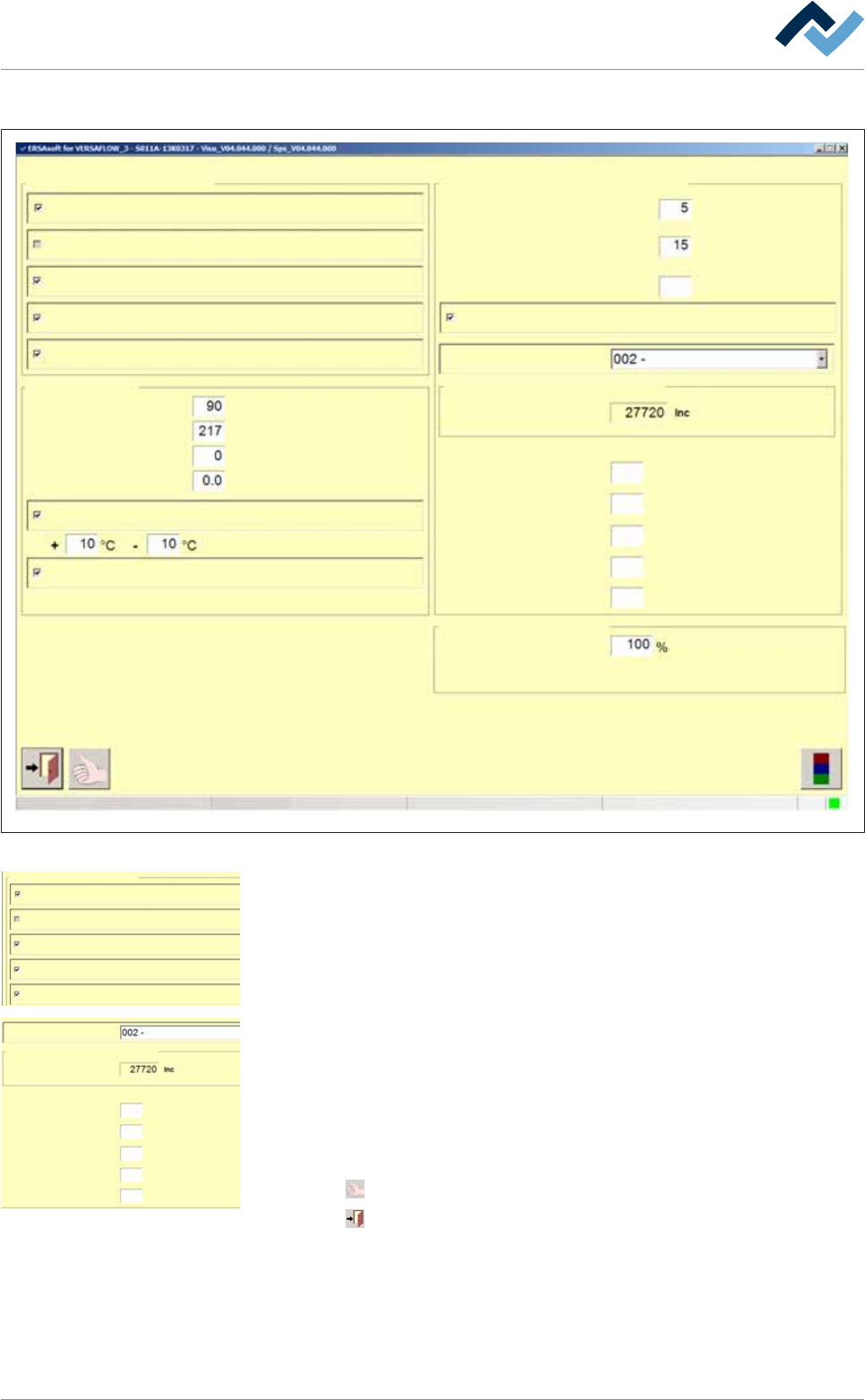
ð The [Soldering module] window appears:
Settings Soldering unit 2 Solder pot 1
Monitorings
user:
none
Maintenance mode
Solder level maximum
Solderbar feeder
Solder level minimum
Solder pot
Preheating time
Module tests
Numbers of Boards
Drive to test position without lowering
Mode gap for solder level
test
Max. duration
Supply
Backstroke
Break
s
Solder wire
75
Time until test
Wave power
Solderlevel ok
s
s
s
s
pcs
min
%
Wave height
min
Solder melting temperature
Standby temperature
Temperature correction
Tolerance message
Broken TC message
°C
°C
°C
Gap for single solder supply
Wave height test
Supply time
Actual value
Solder pot roll in/out
Maximum speed
60
2.0
0.5
2
33.0
Fig.78: The [Soldering module] setting dialog
Monitorings
Solder level maximum
Solderbar feeder
Solder level minimum
Solder wire
Wave height
c) In the [Monitorings] frame enable the following checkboxes:
ð [Solder level minimum]: It is crucial for the automatic test run.
ð [Solder wire]: It monitors whether a solder bar is available.
ð [Solderbar feeder]: It monitors the end positions of the automatic cylinders
on the solder feed.
Mode gap for solder level
test
Max. duration
Supply
Backstroke
Break
s
Solderlevel ok
s
s
s
s
Gap for single solder supply
Wave height test
Supply time
Actual value
60
2.0
0.5
2
33.0
d) In the [Module tests] frame from the [Mode gap for solder level test] drop-
down menu select [Gap for single solder supply].
e) In the [Supply time] frame enter the times for [Max. duration], [Supply], [Back-
stroke], [Solderlevel ok] and [Break] as per margin.
ð These values may be fine-tuned later.
ü Accept settings, close dialogs
a) Click on
to accept a setting.
b) Click on
to close a dialog.
Ersa GmbH Operating Instructions_VF335_en|Rev. 14|30/11/2017 276/695