Operating Instructions_VF335_en.pdf - 第602页
9|Spare and wear parts Compressed air heating, view [Z], [Y] 1 2 2 3 3 Fig.321: EM113-52-00Aa Pos Description Item number A B 1 Tubular heating element 2,5 kW 176974 x 2 Thermocouple, shaped 6IN774_11 x 3 Groove nut, …
9|Spare and wear parts
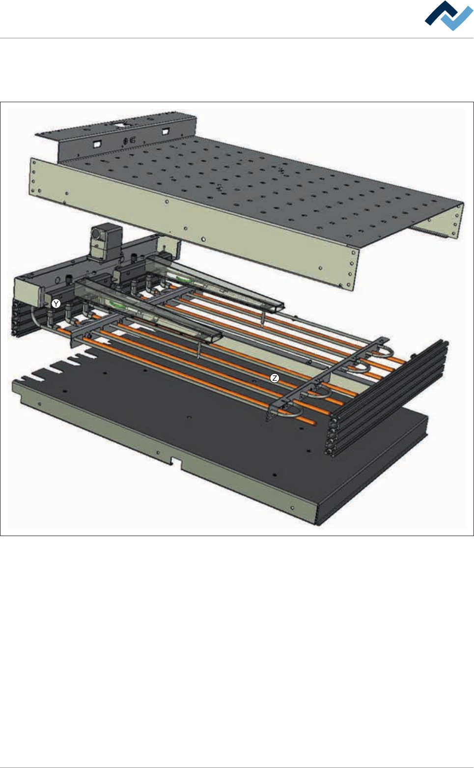
9.7.4 Compressed air heating
Overview
Fig.320: EM113-52-00A
Ersa GmbH Operating Instructions_VF335_en|Rev. 14|30/11/2017 601/695
9|Spare and wear parts
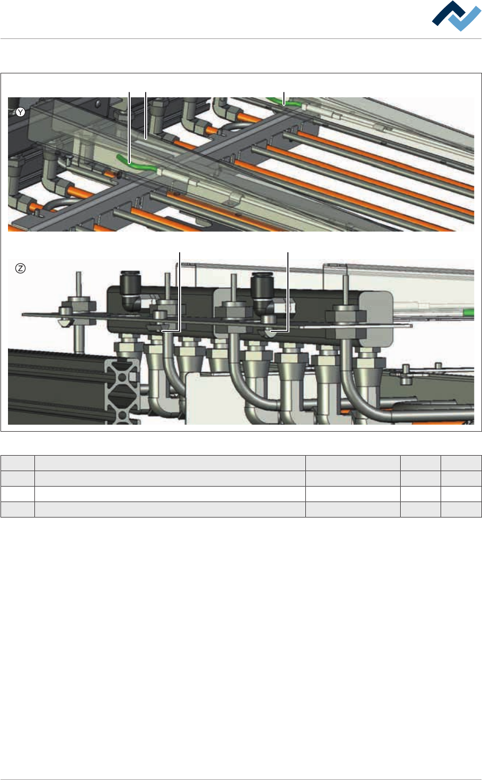
Compressed air heating, view [Z], [Y]
1 22
3 3
Fig.321: EM113-52-00Aa
Pos Description Item number A B
1 Tubular heating element 2,5 kW 176974 x
2 Thermocouple, shaped 6IN774_11 x
3 Groove nut, flute width 5 M5 6ZIS022 x
Ersa GmbH Operating Instructions_VF335_en|Rev. 14|30/11/2017 602/695
9|Spare and wear parts
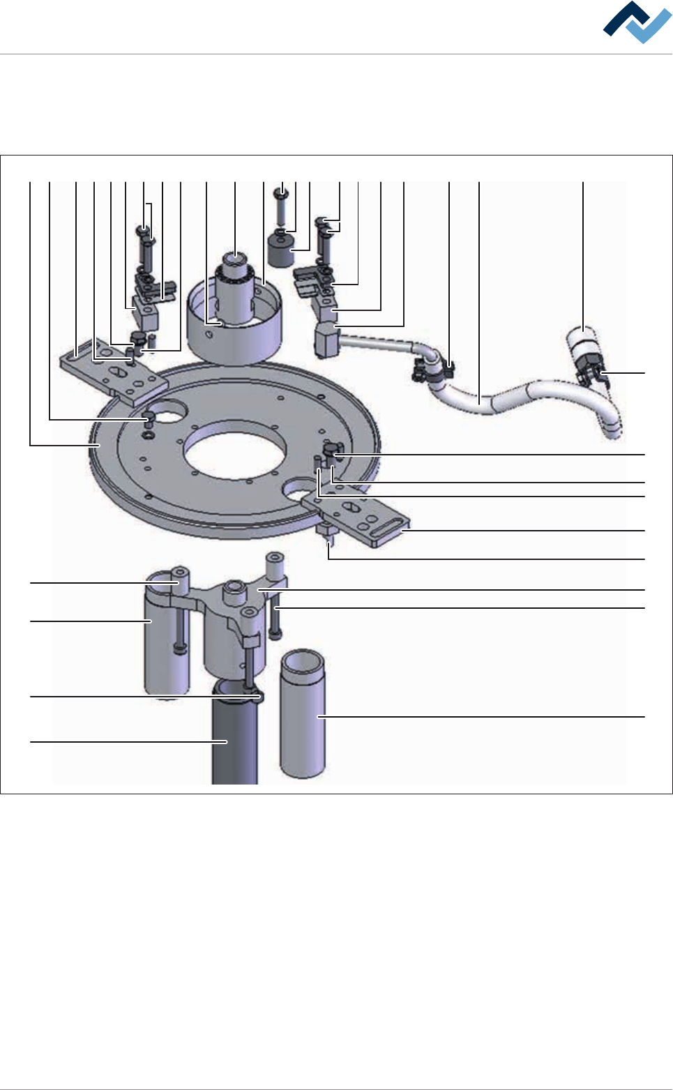
9.8 Selective soldering modules and options
9.8.1 Solder pot cover, centric
1 613 84
2
4
3
13
9
14
16
21
15
17
18
21
227 2624 253 22 2059 23 262610 12 11 19
5
Fig.322: EM1500-127-00B
Ersa GmbH Operating Instructions_VF335_en|Rev. 14|30/11/2017 603/695