Operating Instructions_VF335_en.pdf - 第417页
8|Service and maintenance e) Move the screws of the bayonet catches one after the other with a suitable tool. While doing so, press the nozzle plate slightly downwards. ð As a result, the nozzle plate is completely low…
8|Service and maintenance
Assembling the nozzle plate
A A X
1
2
3
4
5
11
6
7
8
9
10
12
13
14
15
16
17
18
1
X
B
C
B
D
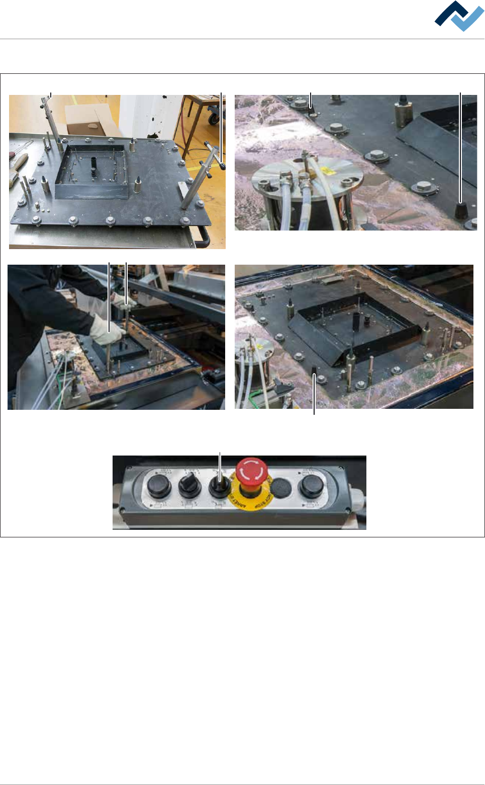
Fig.158: Assemble the nozzle plate. Always hold bolted removing tools by the upper toggle (A)!
ü To assemble the nozzle plate:
ü Both removing tools are mounted on the nozzle plate and locked.
ü The top edge of the pressure chamber is completely covered with solder and
free from oxides and solder dross.
ü The bayonet catches were aligned in such a way that the slots of the screws
run parallel to the edges of the nozzle plate.
a) Risk of accident! Check the locks for tightness again!
b) Lift the nozzle plate holding it with both hands by the upper toggles (A).
ð Risk of accident! Always hold bolted removing tools by the upper toggle
(A)!
c) Place the nozzle plate very slowly on the solder surface and position it carefully
using the coding keys (X).
ð If the machine has the [Setup control] option:
d) Insert the RFID chips into the chip reader.
Ersa GmbH Operating Instructions_VF335_en|Rev. 14|30/11/2017 416/695

8|Service and maintenance
e) Move the screws of the bayonet catches one after the other with a suitable
tool. While doing so, press the nozzle plate slightly downwards.
ð As a result, the nozzle plate is completely lowered onto the pressure cham-
ber.
f) Turn the rotary switch (D) on the control console clockwise.
ð This will turn on the solder wave. Do not operate the pump unnecessarily
long without nitrogen gassing. Otherwise, an unnecessarily large amount
of solder dross is generated.
g) Wait for approximately 10 minutes until the nozzle plate has warmed up and
the solder has reached its target temperature again.
h) Remove the removing tools.
i) Secure the nozzle plate using the socket spanner as shown.
j) When fixing the nozzle plate, always start at zero point (C) and proceed accord-
ing to the numbering shown.
k) Clean all inlet holes with a circular brush.
l) Visual inspection of the solder wave height:
ð Nozzles must be uniformly filled with solder; the wave height must be the
same for each nozzle.
ð The process has now been completed.
Ersa GmbH Operating Instructions_VF335_en|Rev. 14|30/11/2017 417/695
8|Service and maintenance
Inserting the solder pot into the machine
NOTE
To move the DIP solder pot out of the service position, acknowledge the service
message
To be able to move the DIP solder pot out of the service position, acknowledge the
corresponding service message. Afterwards, you will have five minutes to move the
DIP solder pot out of the service position. During this time, a corresponding notice will
be displayed. If the DIP solder pot has not been moved after this time, a timeout mes-
sage appears. After acknowledging the timeout message, you will have another five
minutes to move the DIP solder pot out of the service position.
2
34 4 4
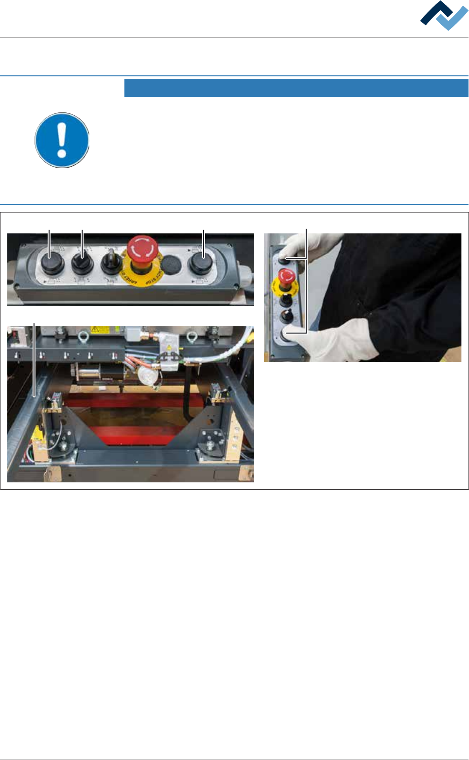
Fig.159: Inserting the solder pot into the machine
ü To insert the solder pot into the machine:
a) Turn the switch (3) to the position shown on the control console.
b) Press and hold both buttons (4) simultaneously.
ð The solder pot is now conveyed into the machine and will stop automatic-
ally in its end position.
c) Release the buttons (4).
d) Remove the solder pot trestle (2).
e) Close all hoods and doors.
f) Terminate the module service.
ð The process has now been completed.
Ersa GmbH Operating Instructions_VF335_en|Rev. 14|30/11/2017 418/695