Operating Instructions_VF335_en.pdf - 第173页
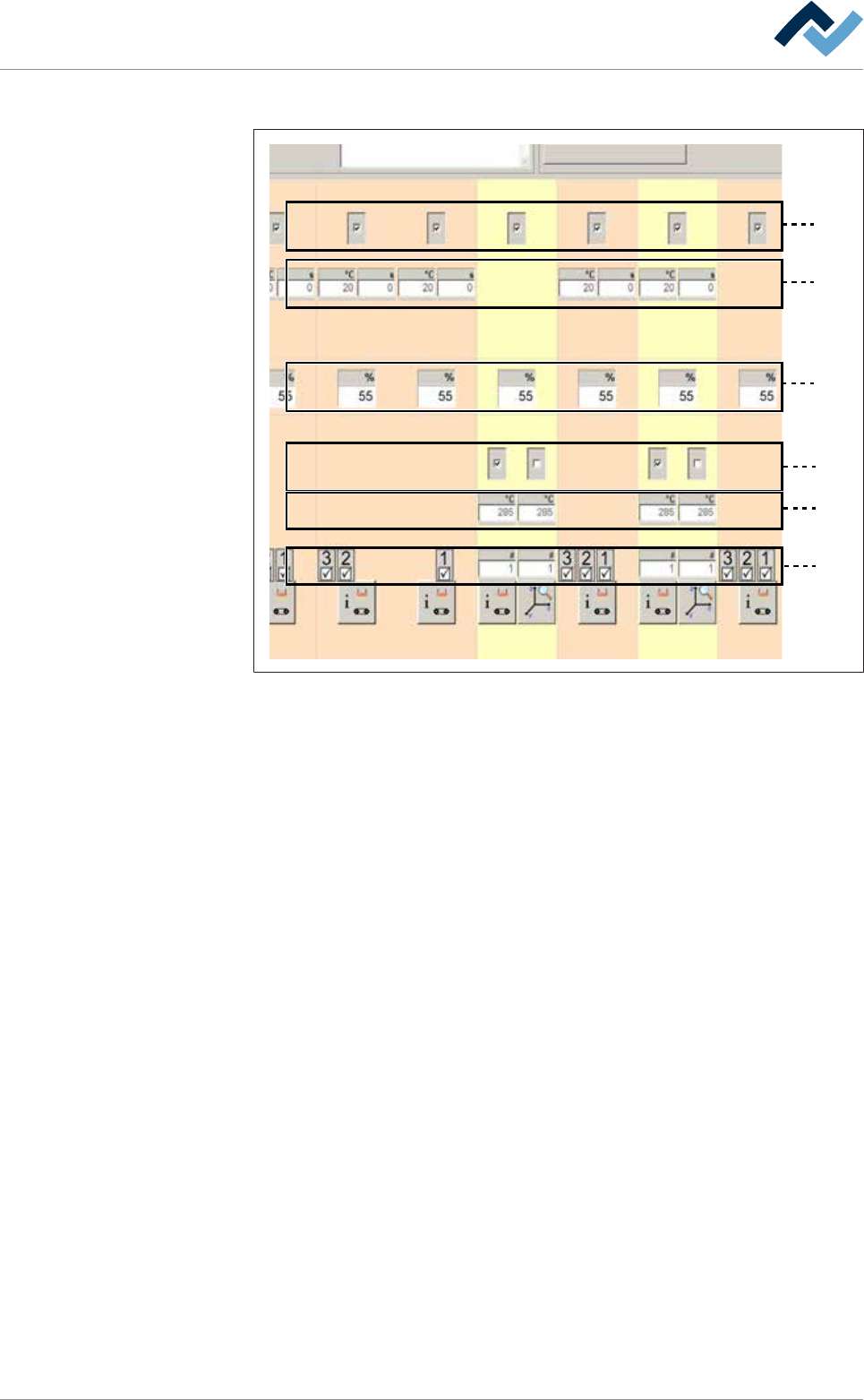
6|Function description Each module features up to six levels: 1 2 3 4 5 6 Fig.36: The module levels – Level 1: In this level, you can enable the module. When a module has been ac- tivated, a checkmark appears. – Level…
6|Function description
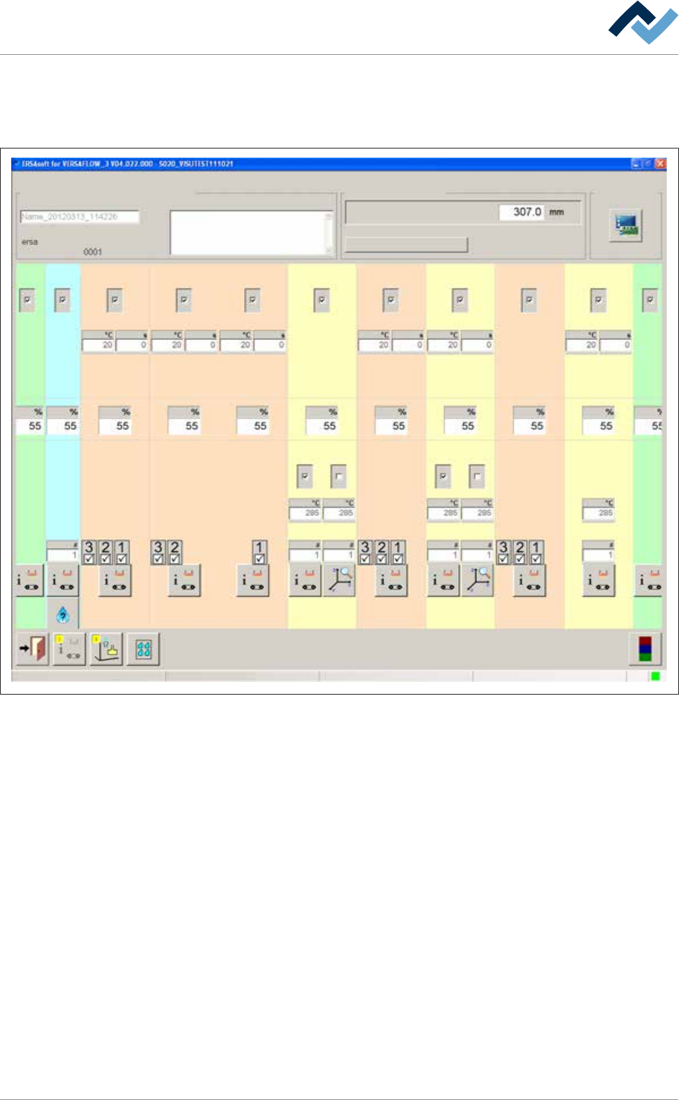
6.9.5 The setting options in the [General soldering program data]
The central part of the [General soldering program data] dialog is divided into sev-
eral registers (columns). Each register represents a module:
Infeed
user: Maintenance mode
ersa
Soldering program editor General soldering program data
Program informations
Program name
Version:
Last modification by:
Infotext:
Conveyor
Conveyor width adjustment
Graphical data
Process time
Fluxer unit Preheating Preheating Preheating Preheating PreheatingSoldering module Soldering module Soldering module Exit
Solder pot Solder pot
21 12 11 1 2 361
1 2 21
41
Change settings for a module within a register. By clicking on the button at the bot-
tom end of a register, you reach a further dialog related to the module.
Ersa GmbH Operating Instructions_VF335_en|Rev. 14|30/11/2017 172/695
6|Function description
Each module features up to six levels:
1
2
3
4
5
6
Fig.36: The module levels
– Level 1: In this level, you can enable the module. When a module has been ac-
tivated, a checkmark appears.
– Level 2: Preheaters above. In this level, you can set the preheater temperat-
ures and process time.
– Level 3: Conveyor sections. In this level, you can set the conveyor speed of the
module.
– Level 4: In this level, you can enable the pot. In double pot soldering modules
(optional), you can enable one or two pots. When a pot has been enabled, a
checkmark appears.
– Level 5: Soldering temperature. In this level, you can set the soldering temper-
ature.
– Level 6: Solder nozzle number: In the case of a soldering module, you can set
the solder nozzle number in this field.
– Level 6: Spray nozzle number. In the case of a fluxer module, you can set the
spray nozzle number in this field.
– Level 6: In the case of a segmented pre-heat module, you can enable the indi-
vidual segments of the heat cartridge. When a segment has been enabled, a
checkmark appears.
6.9.6 Infeed unit settings
No settings can be entered into this dialog.
Ersa GmbH Operating Instructions_VF335_en|Rev. 14|30/11/2017 173/695
6|Function description
6.9.7 Fluxer unit settings
Enabling the module
ü To enable the module:
a) In the [General soldering program data] dialog, activate the checkbox of the
module in level 1.
ð The module has now been enabled and is used in the soldering program.
Setting the conveyor speed
ü To set the conveyor speed:
a) In the [General soldering program data] dialog in level 3, click on the input field
of the conveyor section.
b) Enter the conveyor speed in [%] of the maximum possible speed value.
ð This is the speed at which the board is conveyed into the next module.
Entering the number of the fluxer nozzle used
ü To enter the number of the fluxer nozzle used:
a) In the [General soldering program data] dialog in level 6, click on the input field
of the fluxer nozzle and enter the number of the fluxer nozzle used.
ð Spraying is done with this nozzle.
Performing extended settings in the [General additional data] dialog
ü To perform extended settings:
a) Open the [General soldering program data] dialog.
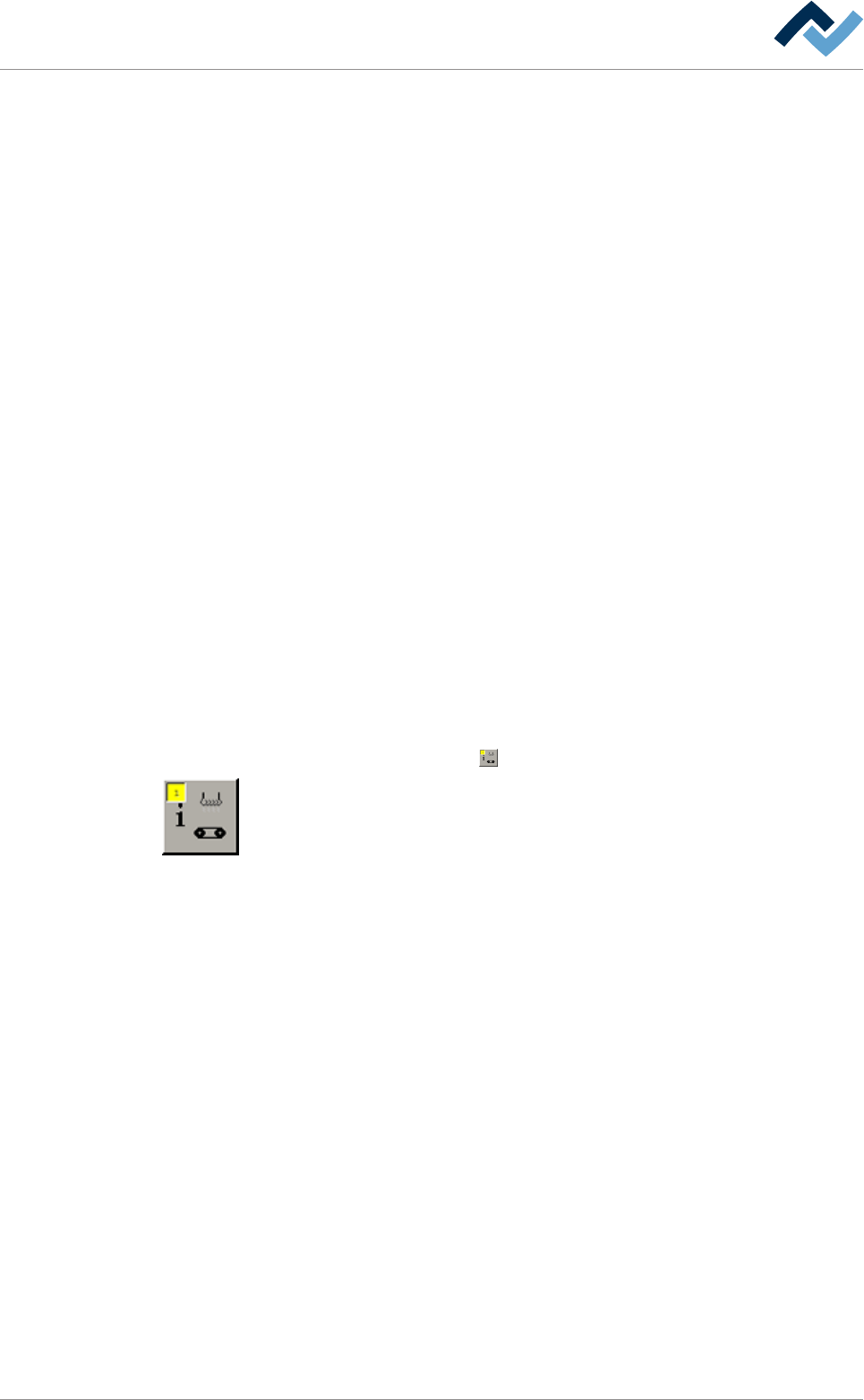
b) Below Level 6, click on the
button in the corresponding module.
Open the [General additional data] dialog. The yellow square provides information
about how often the dialog has already been opened.
Ersa GmbH Operating Instructions_VF335_en|Rev. 14|30/11/2017 174/695