Operating Instructions_VF335_en.pdf - 第182页
6|Function description user: ersa Soldering program editor General additional data Program informations Program name Version: Last modification by: Infotext: Conveyor Conveyor width adjustment Graphical data Process ti…
6|Function description
6.9.9 Soldering unit settings
In this example, the soldering module is provided with a compressed air heater
above and two pots.
Enabling the module
ü To enable the module:
a) In the [General soldering program data] dialog, activate the checkbox of the
module in level 1.
ð The module has now been enabled and is used in the soldering program.
Setting preheating temperature, preheating period
ü To set the preheating temperature and period:
a) In the [General soldering program data] dialog in level 2, click on the input
fields and enter the preheating temperature in [°C] and the prehating period in
[s].
ð The PCBs will thus be subjected from above to the preheating temperature for
the duration of [Preheating time].
Setting the conveyor speed
ü To set the conveyor speed:
a) In the [General soldering program data] dialog in level 3, click on the input field
of the conveyor section.
b) Enter the conveyor speed in [%] of the maximum possible speed value.
ð This is the speed at which the board is conveyed into the next module.
Enabling pots
ü To enable one or both pots:
a) Enable checkboxes in the [General soldering program data] dialog in level 4.
ð If a checkbox is enabled, the relevant pot is used in the soldering program.
Performing extended settings in the [General additional data] dialog
ü To perform extended settings:
a) Open the [General soldering program data] dialog.
b) Below Level 6, click on the
button in the corresponding module.
Open the [General additional data] dialog. The yellow square provides information
about how often the dialog has already been opened.
Ersa GmbH Operating Instructions_VF335_en|Rev. 14|30/11/2017 181/695
6|Function description
user:
ersa
Soldering program editor General additional data
Program informations
Program name
Version:
Last modification by:
Infotext:
Conveyor
Conveyor width adjustment
Graphical data
Process time
General additional data
Park position
Empty module always
80
Process time
Fix horizontal permanently
Data source
Board deflection
Correction
Congestion position
Maintenance mode
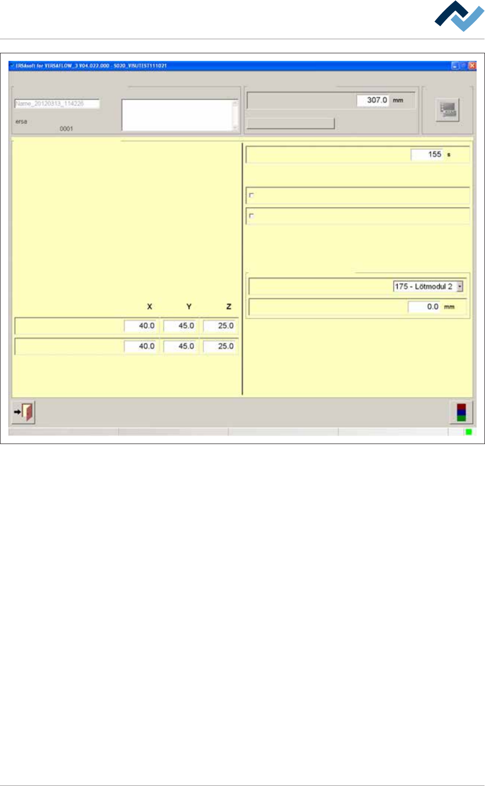
Fig.40: The [General additional data] dialog
Park position and jam position
In the [Park position] input fields, you can define a position for the nozzle, which is
always approached when the process step has been finished. In this position, the
module waits for the next board. You can also approach this position manually.
In the [Congestion position] input fields, you can define a position for the nozzle,
which is always approached when the machine is somewhere congested with
boards.
Adjusting the process time manually
ü To adjust the process time manually:
a) Click on the [Process time] input field and enter a process time.
ð The process time is adjusted, and the time calculated by the controller for this
module is overwritten. When clicking on [Process time], the controller recalcu-
lates all process times. The process time adjusted by you is overwritten.
First always empty the next module
ü The PCBs shall only be fed into the next module if this module is empty:
a) Activate the [Empty module always] checkbox.
Ersa GmbH Operating Instructions_VF335_en|Rev. 14|30/11/2017 182/695

6|Function description
ð The PCBs will only be fed into the module it the next module is empty. This
way, the PCBs are prevented, for example, from remaining too long in the
module due to a jam. However, this function can extend the cycle times.
Permanently fixing PCBs
ü To permanently fix PCBs during processing:
a) Activate the [Fix horizontal permanently] checkbox.
ð The PCBs are aligned in the module and then laterally fixed until processing is
completed. If the checkbox is not activated, the PCBs are only aligned and then
released again. You can activate this function separately for all available fluxer
and soldering modules
Manually compensating for the PCB deflection
Due to the heating and weight of the components, the PCBs get bent during pro-
cessing. Thereby, the distance [Z] from the solder nozzle to the soldering joint
changes. The machine corrects this error if an offset value is specified. The control-
ler takes into account the deflection and corrects the distances accordingly.
ü To compensate the [Board deflection] in machines without deflection measure-
ment:
a) Select the current soldering module from the [Data source] dropdown menu.
b) Determine the deflection of the board at the point of greatest deflection. This
is generally a point in the middle of the PCB.
c) Enter the deflection in [mm] into the [Correction] input field. Enter a positive
value if the board bends downwards. Enter a negative value if the board bends
upwards.
ð The deflection of the board is now taken into account by the controller and the
[Z] distances to the solder joints are corrected accordingly.
Click on
to close the dialog.
Ersa GmbH Operating Instructions_VF335_en|Rev. 14|30/11/2017 183/695