Operating Instructions_VF335_en.pdf - 第258页
6|Function description m) Click on the [Active nozzle] checkbox. ð A [X] is displayed. Your solder nozzle is installed and activated. ü Accept settings, close dialogs a) Click on to accept a setting. b) Click on to clo…
6|Function description
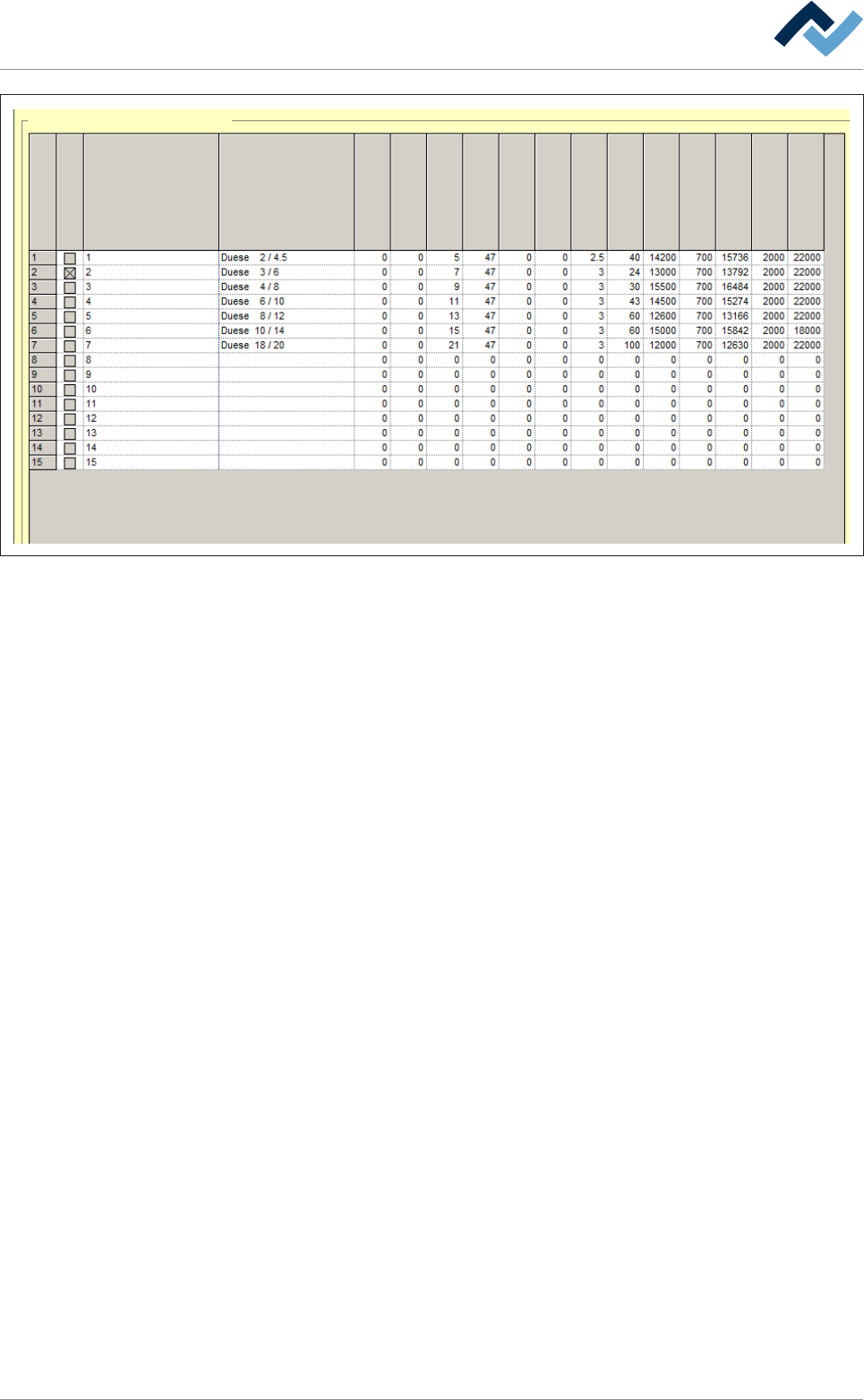
Data table solder nozzle
Active nozzle
Name
nozzle number
Description
X [mm]
Y [mm]
Dimension Y [mm]
Dimension Z [mm]
Offset test...
Offset test...
Y [mm]
X [mm]
Test distance [mm]
Gradient
Offset cold
Test tolerance minus
Offset warm
Test tolerance plus
Test offset max.
Fig.70: The solder nozzle data table. The values for 7 commonly used, rotationally symmetric nozzles are already stored in the fact-
ory. Do not overwrite these values; they serve as reference points for newly added nozzles.
f) On a blank line, click on the [Description] input field and enter a descriptive
text. Basically, it is recommended entering the inner and outer diameters and
the height of the nozzle.
ð If the nozzle is rotationally symmetrical, you can take no account of the [X
[mm]] and [Y [mm]]input fields (0).
ð If the nozzle is not rotationally symmetrical:
g) Determine the centre of the nozzle and enter the values into the [X [mm]] and
[Y [mm]] input fields.
h) Determine the outer diameter of the nozzle and add the measured result [1
mm]. Enter the calculated value into the [Dimension Y [mm]] input field.
i) Determine the height of the nozzle and enter the value into the [Dimension Z
[mm]] input field.
j) From the factory stored nozzles, select one the measurements of which are as
similar as possible to those of the one to be inserted (choose a smaller rather
than a larger nozzle).
k) Record the [Gradient], [Offset cold], [Offset warm], [Test tolerance minus],
[Test tolerance plus] and [Test offset max.] values registered there in the relev-
ant nozzle input fields.
l) To enter the [Test distance [mm]] value:
ð If the inner diameter of your solder nozzle is smaller than 3 mm, enter [2.5
mm].
ð If the inner diameter of your solder nozzle is larger than or equal to 3 mm,
enter the [3 mm] value.
ð If the inner diameter of your solder nozzle is lrger than 8 mm, enter the
[3.5 mm] value.
Ersa GmbH Operating Instructions_VF335_en|Rev. 14|30/11/2017 257/695

6|Function description
m)Click on the [Active nozzle] checkbox.
ð A [X] is displayed. Your solder nozzle is installed and activated.
ü Accept settings, close dialogs
a) Click on
to accept a setting.
b) Click on
to close a dialog.
Ersa GmbH Operating Instructions_VF335_en|Rev. 14|30/11/2017 258/695
6|Function description
6.15.4.2 Determining the [Warm offset] for a wave power of 1%
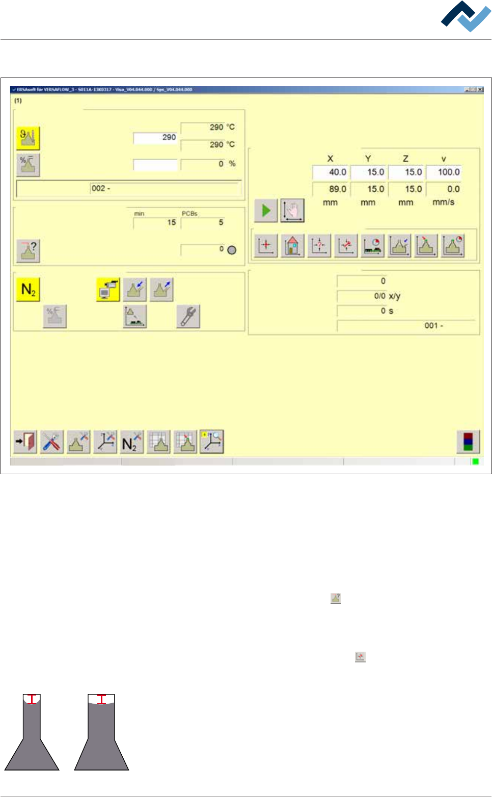
Edit dialog Soldering unit 1 Solder pot 1
Solder pot
user:
none
Maintenance mode
Temperature
Operation mode
Set value Actual value
Solder wave off
Module tests
Next test
Wave offset
Switch functions
Manual movement
Set value
Actual value
Automatic positioning
Set no.
Panel
Remaining time
Active tool
Solder
pot 1
Wave power
1
Fig.71: The [Soldering unit 1 Solder pot 1] input dialog
ü To determine the Wave offset for a wave power of [1%]:
ü You have mounted the nozzle
ü The mounted nozzle has been installed and activated in the Data table solder
nozzle
ü A value of [1%] has been entered into the [Wave power] input field.
a) Enable the solder wave.
b) In the [Module tests] frame, click on the
button.
ð A solder wave height test is performed. As soon as the solder wave
touches the test needle, the [Wave offset] status indicator lights up green.
Wait until the solder wave height test has been completed.
c) In the [Manual movement] frame, click on the
button.
ð The solder pot is moved to the [Service] position.
4 mm
d) Check the height of the wave in the nozzle. With a 1% wave power of the max-
imum value, the solder should be in the middle of the nozzle, about 4 mm un-
der the upper edge of the top. In a narrow nozzle, the solder is drawn by capil-
lary action upwards to the sides, while this effect is slighter in a wide nozzle.
Ersa GmbH Operating Instructions_VF335_en|Rev. 14|30/11/2017 259/695