Operating Instructions_VF335_en.pdf - 第198页
6|Function description 2 Soldering module data set (single pot) [ } 194] Ersa GmbH Operating Instructions_VF335_en|Rev. 14|30/11/2017 198/695
6|Function description
6.9.12.3 Soldering module data set (double pot)
In this variant, two pots are located on the axis system. In addition, in the table of
coordinates, the [Tool] register appears again if both pots have been enabled in the
[General soldering program data] dialog.
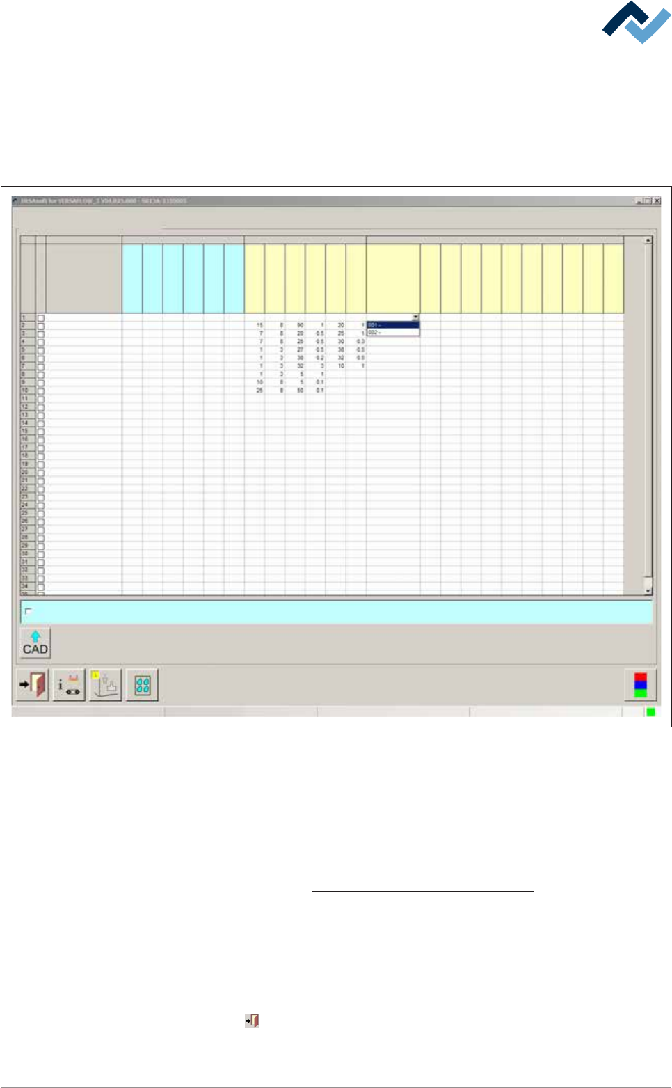
Please observe the following picture:
Set data
Set dataSoldering program editor
Fluxer coordinates relate to nozzle 1
user: Service Maintenance mode
Set
Hide
Description
Endposition X [mm]
Endposition Y [mm]
Speed X/Y [mm/s]
mode
Spray amount [%]
Spray time [s]
Flux unit Soldering unit 1 Soldering unit 2
Solder pot 1
Solder pot 2
Endposition Z [mm]
Speed Z [mm/s]
Wave height [%]
Soldering time [s]
Lower value
Lowering time [s]
Tool
Z while moving [mm]
Endposition X [mm]
Endposition Y [mm]
Speed X/Y [mm/s]
Endposition Z [mm]
Speed Z [mm/s]
Wave height [%]
Soldering time [s]
Lower value
Lowering time [s]
Fig.45: Data sets: Soldering module 2 has two solder pots in this example.
Entering target coordinates
ü To enter target coordinates in case of a double pot:
a) In the [General soldering program data] dialog, enable both pots and then
open the [Set data] dialog.
b) Enter target coordinates and parameters in the table. With regard to this,
please read the Soldering module data set (single pot) [
}194] chapter.
ð An additional [Tool] register appears now in the table.
c) Click on a cell in the [Tool] register.
ð A dropdown menu appears in the cell.
d) Select the pot to be used for soldering in the dropdown menu.
ð The process has now been completed.
Click on
to close the dialog.
Also see
Ersa GmbH Operating Instructions_VF335_en|Rev. 14|30/11/2017 197/695

6|Function description
6.9.12.4 Importing from CAD data
You can import data sets from the CAD AssistantERSAcad directly into the soldering
program. Please refer to the functional description of the CAD Assistant ERSAcad.
ü Importing CAD data:
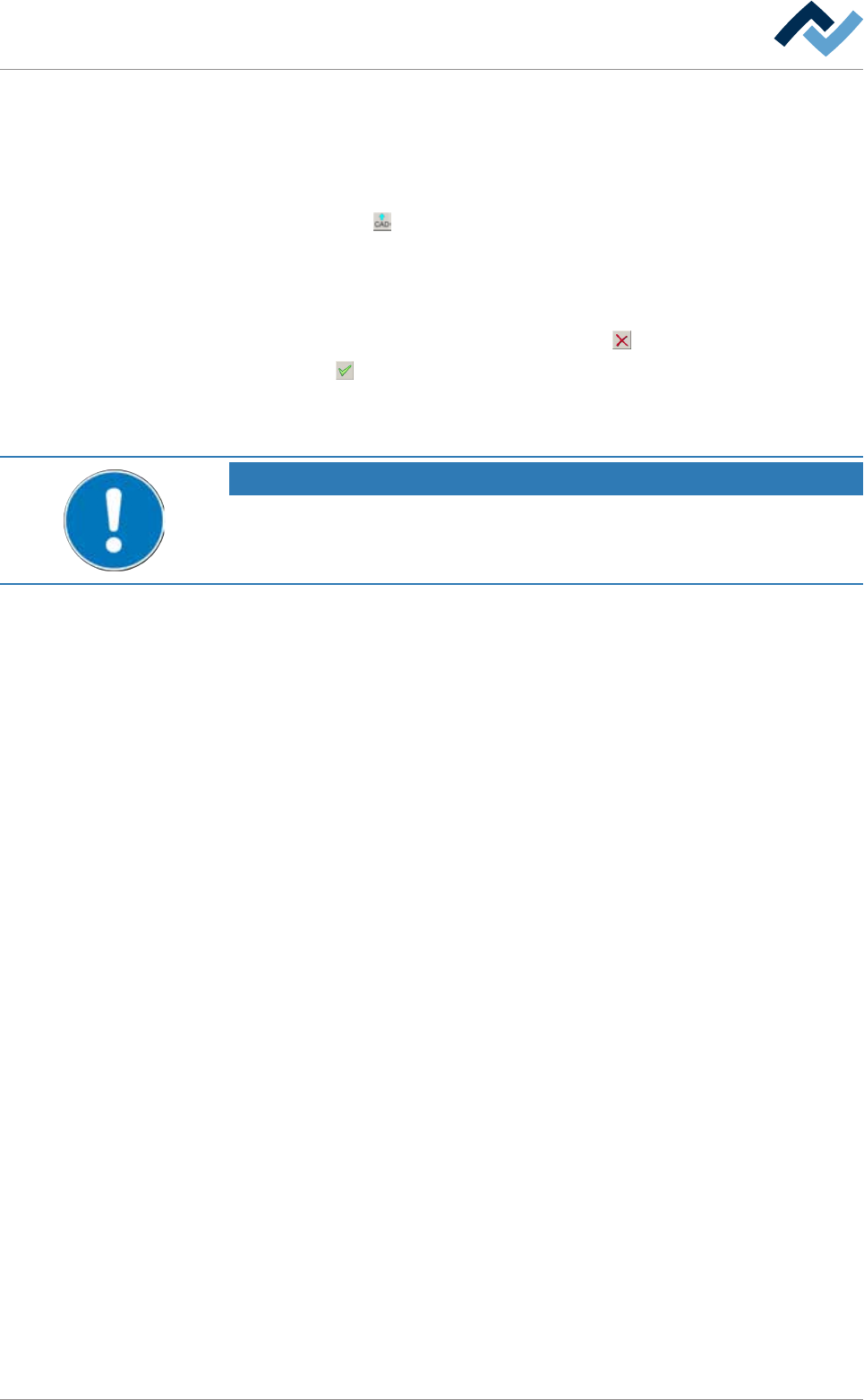
a) Click on the
button in the bottom toolbar of the [Set data] dialog.
ð The [Load file] dialog is displayed:
b) Select a file from the list.
ð The file identification is displayed in the upper input field of the dialog.
c) Should the process be cancelled, click on the
button or
d) on the
button.
ð The file is loaded and the data sets are immediately transferred to the solder-
ing program. You can edit each data set, if required.
NOTE
Caution when importing!
Data must be available in the [.csv] format. If you import data sets, all available data
sets are overwritten.
Ersa GmbH Operating Instructions_VF335_en|Rev. 14|30/11/2017 199/695