Operating Instructions_VF335_en.pdf - 第262页
6|Function description c) Read the new value and compare it with the value you noted down. The new value may differ by ± 1% from the value noted down. ð If the discrepancy is more than + 1% of the value you noted down:…
6|Function description
6.15.4.3 Determining [Warm offset] for a 75% wave power and adjusting the
gradient
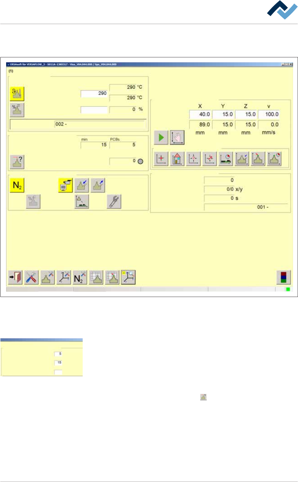
Edit dialog Soldering unit 1 Solder pot 1
Solder pot
user:
none
Maintenance mode
Temperature
Operation mode
Set value Actual value
Solder wave off
Module tests
Next test
Wave offset
Switch functions
Manual movement
Set value
Actual value
Automatic positioning
Set no.
Panel
Remaining time
Active tool
Solder
pot 1
Wave power
75
Special positions
Fig.72: The [Soldering unit 1 Solder pot 1] input dialog
ü To determine the Wave offset for a wave power of [75%]:
ü You have correctly determined the [Offset warm] value for a wave power of
1%.
Settings Soldering unit 1 Solder pot 1
Monitorings
user:
none
Maintenance mode
Solder level maximum
Solderbar feeder
Solder level minimum
Solder pot
Preheating time
Solder level and wave height test
Numbers of Boards
Drive to test position without lowering
Supply time
Max. duration
Supply
Backstroke
Break
s
Solder wire
75
Time until wave hight test
Wave power
Solderlevel ok
s
s
s
s
pcs
min
%
Wave height
min
Solder melting temperature
Standby temperature
Temperature correction
Tolerance message
Broken TC message
°C
°C
°C
ü In the [Settings Soldering unit 1 Solder pot 1] settings dialog, the [Wave power]
for the solder wave height test has been set to 75%.
ü The mounted nozzle has been created and activated in the Data table solder
nozzle
ü A value of [75%] has been entered into the [Wave power] input field.
a) Enable the solder wave.
b) In the [Module tests] frame, click on the
button.
ð A solder wave height test is performed. As soon as the solder wave
touches the test needle, the [Wave offset] status indicator lights up green.
Wait until the solder wave height test has been completed.
ð In the [Module tests] frame, a new value is now specified for the [Wave
offset]. This value was also automatically transferred to the nozzle table.
Ersa GmbH Operating Instructions_VF335_en|Rev. 14|30/11/2017 261/695
6|Function description
c) Read the new value and compare it with the value you noted down. The new
value may differ by ± 1% from the value noted down.
ð If the discrepancy is more than + 1% of the value you noted down:
d) Open the solder nozzle table and slightly increase the [Gradient] value, at most
by 5 units.
e) If the descrepancy is less than - 1% of the value you noted down:
f) Open the solder nozzle table and slightly reduce the [Gradient] value, at most
by 5 units.
g) Store the entries and re-perform a soldering wave height test.
h) Repeat these steps until the [Wave offset] value lies in the tolerance range.
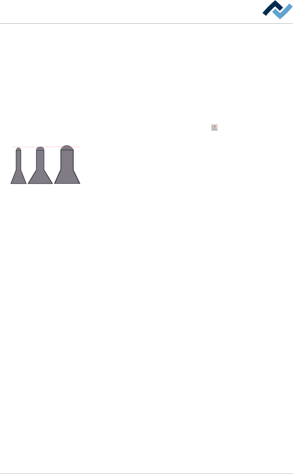
i) In the [Manual movement] frame, click on the
button.
ð The solder pot is moved to the [Service] position.
3 mm
j) Check the height of the wave. In a 75% wave power of the maximum value, the
solder wave should lie still on the nozzle, i.e. make no horizontal or vertical
movement. At the same time, it features a height of about 3 mm.
ð The solder nozzle has been properly installed.
Ersa GmbH Operating Instructions_VF335_en|Rev. 14|30/11/2017 262/695

6|Function description
6.16 Flux unit Flux application module: flux control (option)
Function
The flux control system checks the soldering program in terms of choosing a certain
flux for soldering. If such record is available in the program, the control system
checks which flux is in the tank and compares it with the program data. If data coin-
cide, the program may be used for soldering. If not, a message appears, and the
program cannot be run. For proper functioning, specify the flux in the tank cor-
rectly. Flux can be specified manually or using a code reader.
Before starting operations, please read the For your safety [
}33] chapter and ob-
serve in particular its instructions on how to handle the flux material!
A detailed description of flux refilling can be found in the Supplementing flux ma-
terial storage [}372]chapter.
A detailed description of system cleaning, washing and air removal can be found in
the Disassembling and cleaning the flux material storage tank. [
}364]chapter.
Ersa GmbH Operating Instructions_VF335_en|Rev. 14|30/11/2017 263/695