Operating Instructions_VF335_en.pdf - 第660页
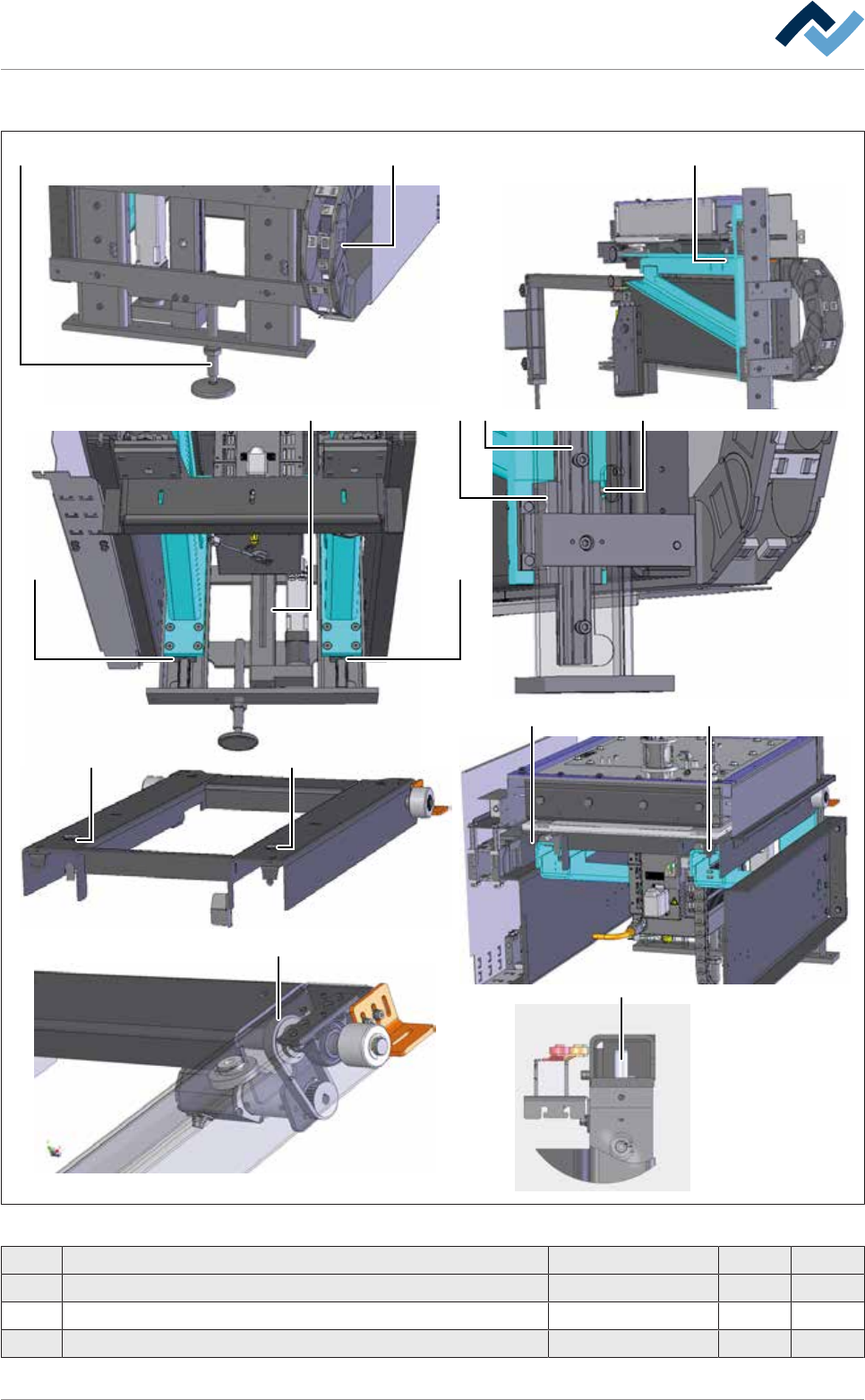
9|Spare and wear parts View [X] 1 2 3 3 8 8 3 6 5 9 4 7 7 1 0 1 1 Fig.375: EM131-61-00a Pos Description Item number A B 1 Adjusting foot 256979 x 2 Energy chain 208191 x 3 Guide wagon 206599 x Ersa GmbH Operating Inst…
9|Spare and wear parts
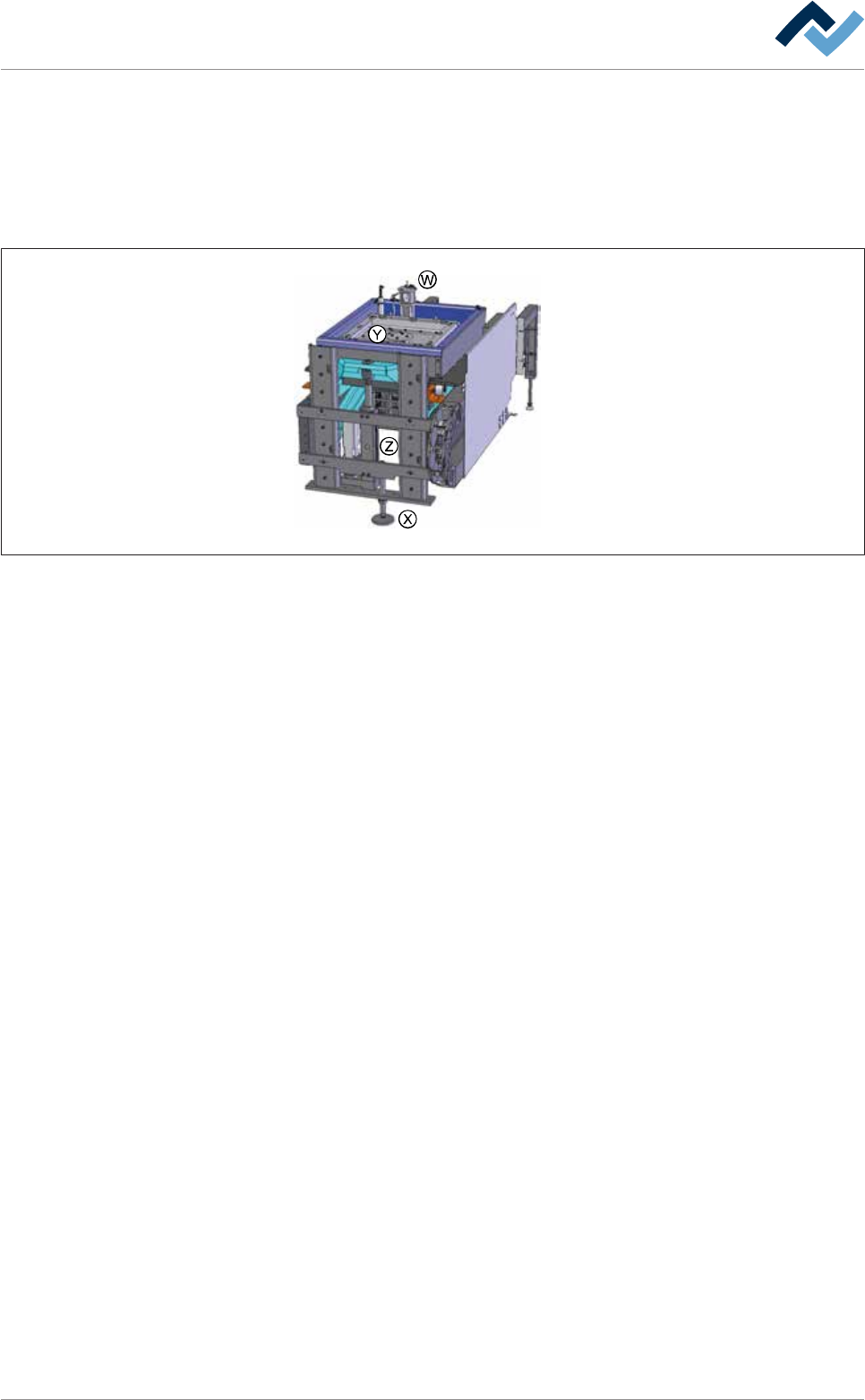
9.9.3 DIP_soldering module (multiwave) XL with induction pump
9.9.3.1 DIP soldering module (multiwave) XL extension unit and Z axis
Overview
Fig.374: EM131-61-00b
Ersa GmbH Operating Instructions_VF335_en|Rev. 14|30/11/2017 659/695
9|Spare and wear parts
View [X]
1 2
33
88
3 6 59
4
77
10
11
Fig.375: EM131-61-00a
Pos Description Item number A B
1 Adjusting foot 256979 x
2 Energy chain 208191 x
3 Guide wagon 206599 x
Ersa GmbH Operating Instructions_VF335_en|Rev. 14|30/11/2017 660/695

9|Spare and wear parts
Pos Description Item number A B
4 Fixation screw M12 206598 x
5 Grease nipple, 90° 6SCHMNI6X1-90 x
6 Guide rail 254961 x
7 Y-Straight support 209052 x
8 Locking ring A30 6SER-A300471 x
9 Electric cylinder ETH080M10 260794 x
10 Cylindrical pin WC12.82.188 x
11 Tooth belt POWER GRIP HTD 6ZR0325-5M-15 x
Ersa GmbH Operating Instructions_VF335_en|Rev. 14|30/11/2017 661/695