Operating Instructions_VF335_en.pdf - 第268页
6|Function description 6.17 Versascan (option) The code reader in the optional Versascan module at the machine infeed reads the codes on the PCBs. As the code reader may be automatically moved, in case of mul- tiple pa…

6|Function description
Production using the soldering program
ü Production start:
ü An acceptable program has been chosen.
a) Run the soldering program.
ð If no flux type is specified in the program, production will start irrespective
of the type of flux in the tank.
b) If a flux material type has been specified in the soldering program, the control
system will check if the data in the [Flux unit 1 - mount data] setting dialog
match those of the soldering program.
ð If data do not coincide, the program will not run and a message will be dis-
played.
ð If data coincide, the program will run.
ð The process has now been completed.
Soldering report data
If you work with a program where a certain flux type is specified, these data will
also be recorded in the soldering report.
Low flux level in the tank
When the flux level is insufficient, a message will appear which shall be acknow-
ledged after flux refilling. If in the [Flux unit 1 - mount data] setting dialog you have
defined a flux material type, an additional message will appear. It prompts you to
specify the flux type in the setting window again. Only then you will be able to ac-
knowledge the message and continue operation. See the section Specifying flux
material type in the setting dialog [Flux unit 1- mount data].
Ersa GmbH Operating Instructions_VF335_en|Rev. 14|30/11/2017 267/695

6|Function description
6.17 Versascan (option)
The code reader in the optional Versascan module at the machine infeed reads the
codes on the PCBs. As the code reader may be automatically moved, in case of mul-
tiple panels it is possible to read the code of each PCB of a workpiece carrier.
Moreover, the code reader reads the master code applied on the workpiece carrier
in order to assign a soldering program to it.
Further, the Versascan module can detect the allocation of the single panels of a
workpiece carrier. Empty panels may thus be excluded from the working cycle and
logging process. The component check function verifies whether the PCB is fully as-
sembled and makes sure that the relevant components are properly positioned.
The Versascan module is operated via an additional control terminal with separate
operating instructions.
NOTE
Additional documents
With regard to the scan module subject, please also read the documents in the
[Code_Scanner] folder on the [product_data_selective] data carrier included in the
scope of delivery.
Ersa GmbH Operating Instructions_VF335_en|Rev. 14|30/11/2017 268/695
6|Function description
6.18 Versaeye inspection system (option)
With the Versaeye inspection system it is possible to inspect the relevant soldering
points automatically. During inspection, it detects any wetting problems, bridges,
solder beads and unsoldered pins.
The Versaeye inspection system is operated via an additional control terminal.
NOTE
Additional documents
As regards the inspection module, please also read the documents [manualHW_E] and
[manualSW_E] in the [Versaeye] folder on the data carrier [product_data_selective],
which is part of the scope of supply.
Display of the Versaeye state
From the start dialog you may view the current state of the Versaeye inspection
system.
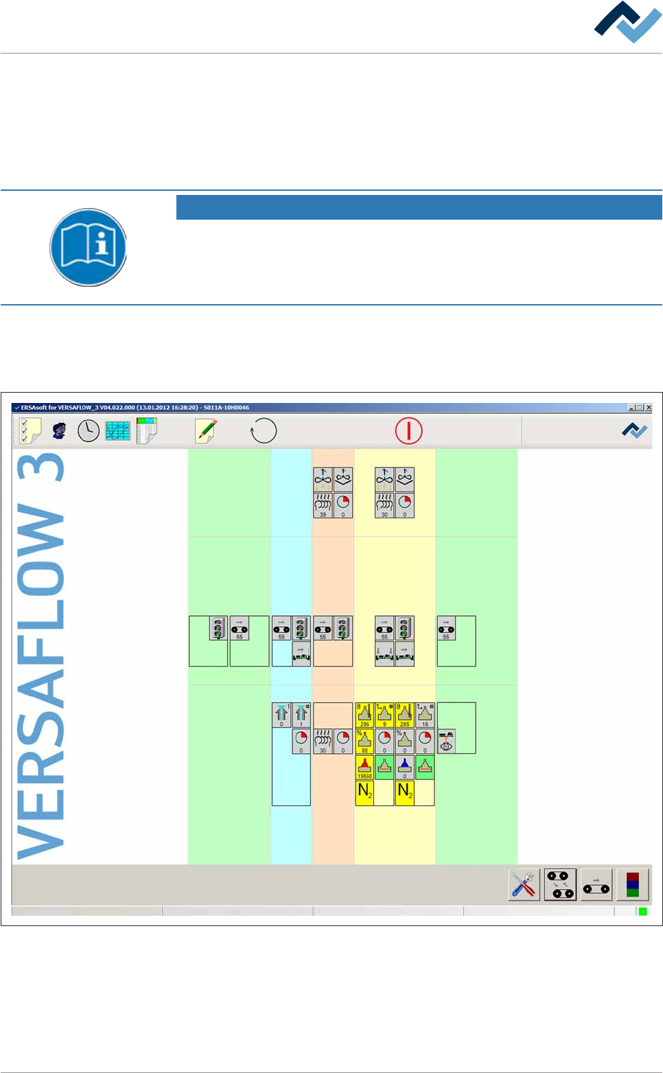
Preheating Soldering module Exit unitInfeed Infeed unit
Solder pot
user: none
Flux unit
Maintenance mode
Exit
Fig.75: The start dialog with a schematic illustration of the machine modules. The Versaeye inspection system is displayed in the
exit unit.
The Versaeye inspection system is represented schematically with a symbol. How-
ever, the module will appear in the start dialogue only if has been marked as avail-
able in the machine configuration.
ü Open the [Exit unit – bottom] input dialog:
Ersa GmbH Operating Instructions_VF335_en|Rev. 14|30/11/2017 269/695