Operating Instructions_VF335_en.pdf - 第672页
9|Spare and wear parts View [W] 8 1 0 1 1 4 5 1 9 3 2 6 7 Fig.387: EM146-61-10-20-00C Pos Description Item number A B 1 Gauge-glass 209190 x 2 Probe 145960 x 3 Isolation 255049 x 4 Reference nozzle 255088 x 5 Graphite…
9|Spare and wear parts
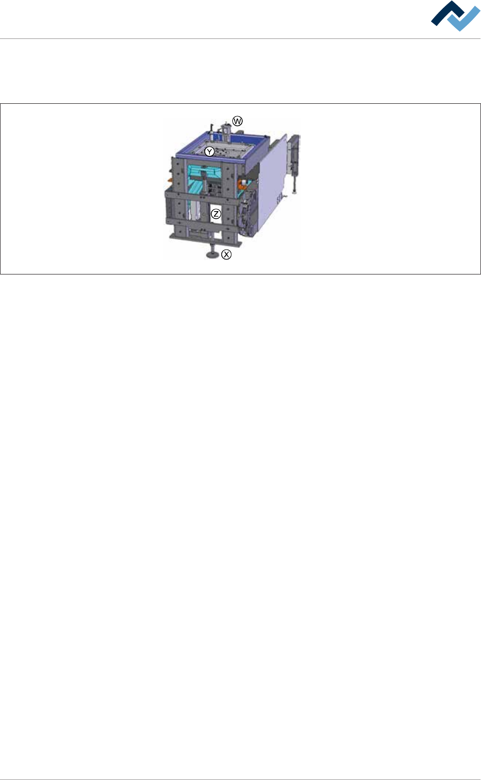
9.9.3.4 DIP soldering module (multiwave) XL wave height measurement
Overview
Fig.386: EM131-61-00b
Ersa GmbH Operating Instructions_VF335_en|Rev. 14|30/11/2017 671/695
9|Spare and wear parts
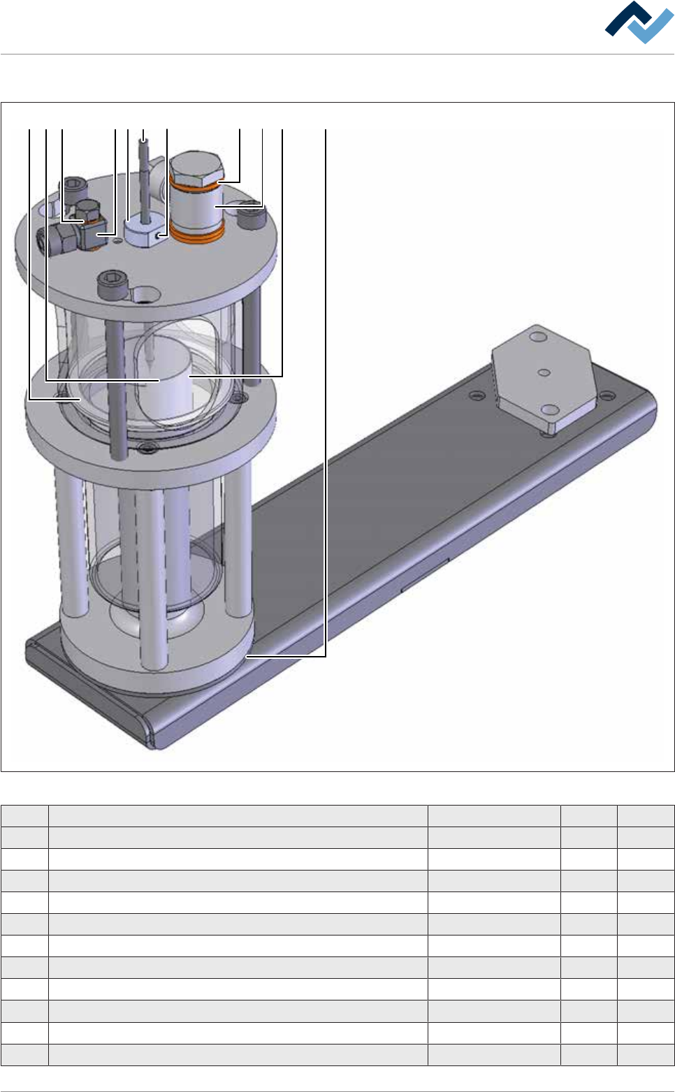
View [W]
8 1011 4 519 3 26 7
Fig.387: EM146-61-10-20-00C
Pos Description Item number A B
1 Gauge-glass 209190 x
2 Probe 145960 x
3 Isolation 255049 x
4 Reference nozzle 255088 x
5 Graphite sealing 209661 x
6 Sealing ring, copper 153612 x
7 Straight screwing M5, stainless steel 6BO116E x
8 Set screw M3 6M03X003E0913 x
9 Sealing ring 296644 x
10 Angular swivel screw connection 6BO102 x
11 Sealing ring, copper G1/4 153647 x
Ersa GmbH Operating Instructions_VF335_en|Rev. 14|30/11/2017 672/695

9|Spare and wear parts
9.9.3.5 XL DIP soldering module (multiwave) setup verification
Item Designation Item number A B
1 Rope tool coding for down holder-XL 322421 X
2 Rope tool coding for nozzle plate-XL 322449 X
3 Rope tool coding splash guard-XL 322427 X
Ersa GmbH Operating Instructions_VF335_en|Rev. 14|30/11/2017 673/695