Operating Instructions_VF335_en.pdf - 第83页
4|Transport, installation, storage, disposal CAUTION Material damage caused by a faulty rotary field, wrong phase voltage or missing N- connection is possible! a) Check the correct voltage phase with a suitable measuri…
4|Transport, installation, storage, disposal
c) Dimension the cross-section of the connection cable according to the machine
connection value!
d) Insert the connecting cable from the bottom through the strain relief fixture
into the control cabinet.
ð The process has now been completed.
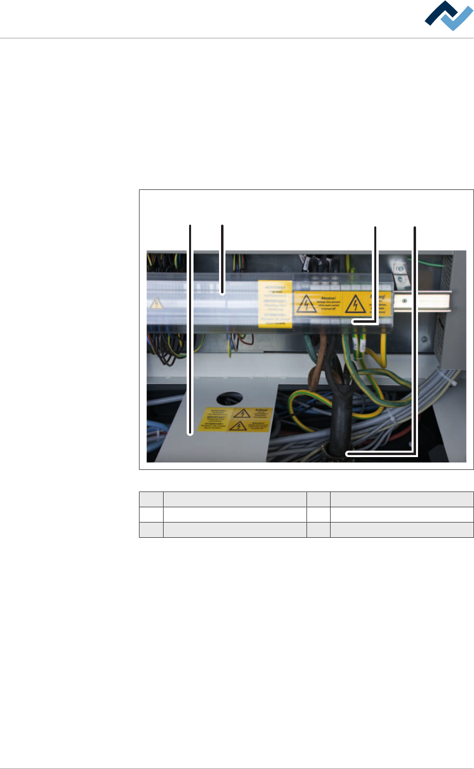
4.11.2 Connecting the power supply
The connections are located at the rear of the machine. They can be accessed after
opening the doors of the control cabinet.
1 2 34
Fig.16: Connecting the power supply
1 Plate 4 Terminal
2 Terminal cover
3 Strain relief
Connect the cable
ü Connect the cable:
a) turn off the machine at the main switch
b) Open the control cabinet doors.
c) Remove the terminal cover.
d) Lead the connecting cable through the strain relief.
e) Read the wiring diagrams provided.
f) Connect the cable to the terminals.
g) Tighten the strain relief.
h) Mount the terminal cover.
ð The power supply is connected.
Ersa GmbH Operating Instructions_VF335_en|Rev. 14|30/11/2017 82/695
4|Transport, installation, storage, disposal
CAUTION
Material damage caused by a faulty rotary field, wrong phase voltage or missing N-
connection is possible!
a) Check the correct voltage phase with a suitable measuring instrument!
b) Check the rotary field. Pay attention to the clockwise rotating field!
c) Check the correct function of the N and PE connection!
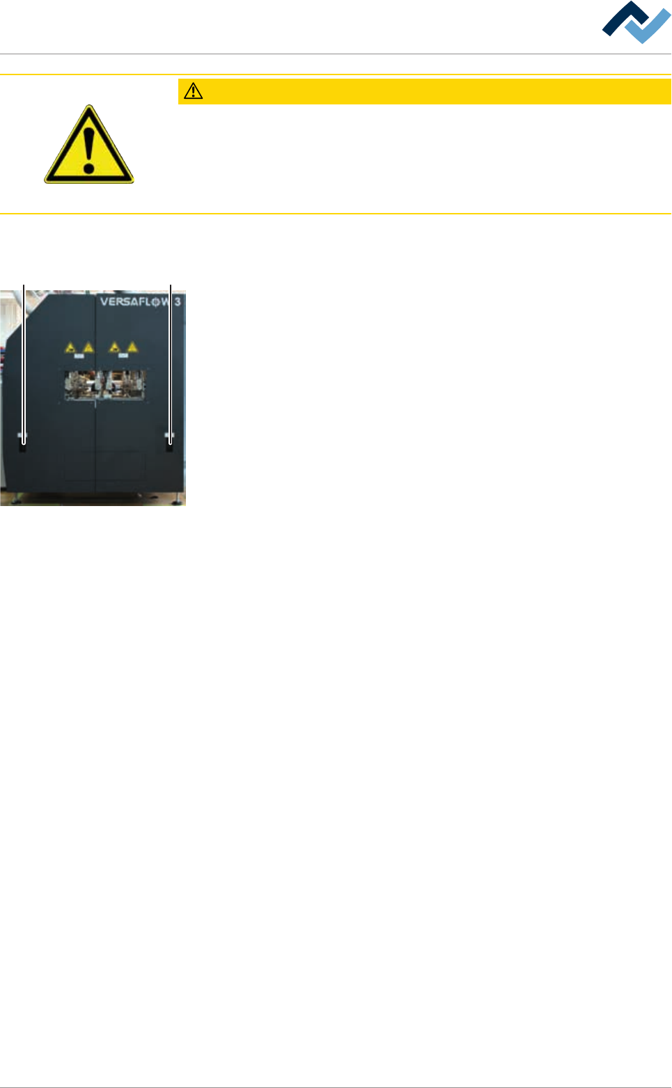
4.11.3 Inline interfaces
5 5
The inline interfaces (5) are located at the machine infeed and outfeed tables. The
connections are inside the machine behind the covering plates.
Ersa GmbH Operating Instructions_VF335_en|Rev. 14|30/11/2017 83/695
4|Transport, installation, storage, disposal
4.11.4 Connecting the suction pipes
WARNING
Severe or fatal injuries from flammable substances!
Operating the machine without suction system is not allowed!
ü Connecting the suction pipes:
a) Read the suction diagrams provided.
ð The suction nozzles are preassembled for aspiration from above.
b) Connect the suction nozzles to the on-site suction system.
ð Always connect all existing suction nozzles!
c) Secure all suction lines with a hose clamp.
d) Switch on the extraction unit.
ð An air flow must be perceived within the machine at all suction points.
ð The process has now been completed.
With regard to this, please read the Extraction capacity [
}26] chapter.
Ersa GmbH Operating Instructions_VF335_en|Rev. 14|30/11/2017 84/695