Operating Instructions_VF335_en.pdf - 第82页
4|Transport, installation, storage, disposal c) Dimension the cross-section of the connection cable according to the machine connection value! d) Insert the connecting cable from the bottom through the strain relief fi…
4|Transport, installation, storage, disposal
DANGER
Possible personal and material damage!
a) For any work performed on the machine itself or on its electric or pneumatic
equipment, locally applicable accident prevention, safety and environmental pro-
tection regulations are to be observed.
b) Make sure that pipes are placed in such a way as to avoid stumbling accidents!
c) Properly assemble all guards and safety devices.
With respect to this, read also chapter Technical data [}25] and the supplied wir-
ing diagrams!
4.11.1 Preparing the electrical connection
DANGER
Dangerous electrical voltage!
Serious injury or death from electric shock!
ü Work on the electrical system or the machine operating equipment must be un-
dertaken only by skilled electricians or by properly trained people under the su-
pervision and guidance of skilled electricians in accordance with the electro-tech-
nical rules.
a) According to VDE 0022 standard, the operator and installer of the system are re-
sponsible for the compliance with EVU and VDE regulations.
CAUTION
Risk of property damages!
ü If the machine has been switched off via the main switch, do not restart it imme-
diately.
a) Wait at least for three minutes!
b) Only when this time has elapsed is it possible to restart the machine!
ð Failure to observe this requirement may lead to damages to the electronic equip-
ment of the machine, to the PC and to the UPS!
When the switch is ON, the panel will not open!
a) Turn the main switch to the OFF position.
b) Open the control cabinet.
Preparing the electrical connection
ü Preparing for connection:
a) retighten all terminal screws in the control cabinet as they could have loosened
during transport.
b) Compare the local mains voltage and the power frequency with the specifica-
tions on the machine rating plate.
Ersa GmbH Operating Instructions_VF335_en|Rev. 14|30/11/2017 81/695
4|Transport, installation, storage, disposal
c) Dimension the cross-section of the connection cable according to the machine
connection value!
d) Insert the connecting cable from the bottom through the strain relief fixture
into the control cabinet.
ð The process has now been completed.
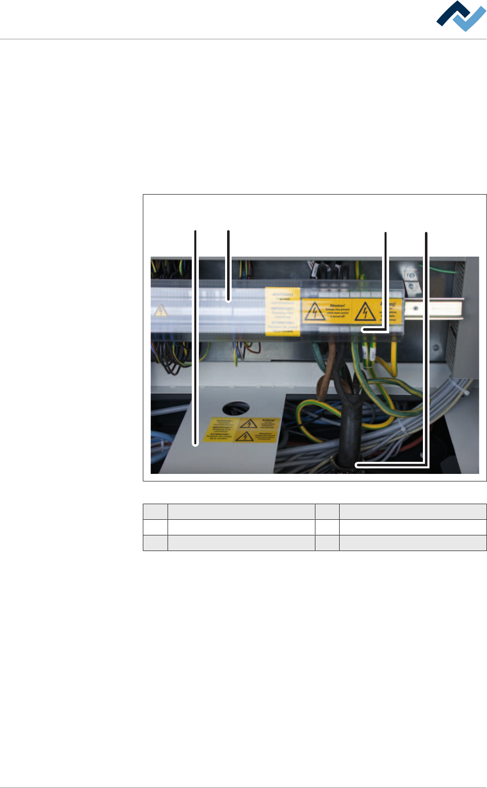
4.11.2 Connecting the power supply
The connections are located at the rear of the machine. They can be accessed after
opening the doors of the control cabinet.
1 2 34
Fig.16: Connecting the power supply
1 Plate 4 Terminal
2 Terminal cover
3 Strain relief
Connect the cable
ü Connect the cable:
a) turn off the machine at the main switch
b) Open the control cabinet doors.
c) Remove the terminal cover.
d) Lead the connecting cable through the strain relief.
e) Read the wiring diagrams provided.
f) Connect the cable to the terminals.
g) Tighten the strain relief.
h) Mount the terminal cover.
ð The power supply is connected.
Ersa GmbH Operating Instructions_VF335_en|Rev. 14|30/11/2017 82/695
4|Transport, installation, storage, disposal
CAUTION
Material damage caused by a faulty rotary field, wrong phase voltage or missing N-
connection is possible!
a) Check the correct voltage phase with a suitable measuring instrument!
b) Check the rotary field. Pay attention to the clockwise rotating field!
c) Check the correct function of the N and PE connection!
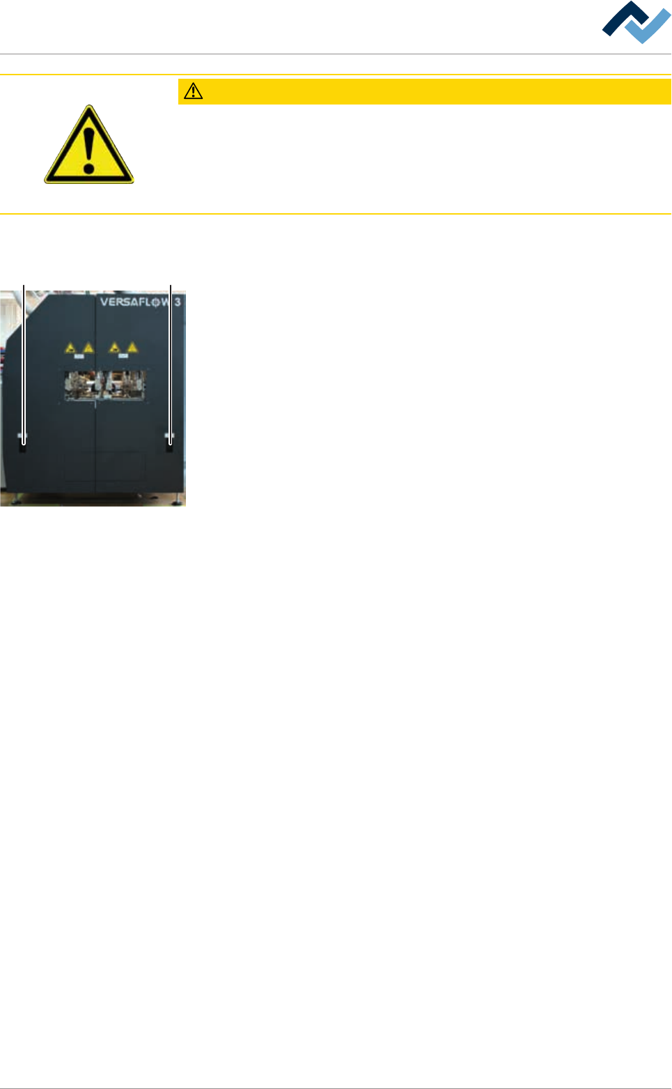
4.11.3 Inline interfaces
5 5
The inline interfaces (5) are located at the machine infeed and outfeed tables. The
connections are inside the machine behind the covering plates.
Ersa GmbH Operating Instructions_VF335_en|Rev. 14|30/11/2017 83/695