Operating Instructions_VF335_en.pdf - 第542页
9|Spare and wear parts 9.5.3.2 Fixed rail 2, (dual track) Overview Fig.263: EM113-30-00 Ersa GmbH Operating Instructions_VF335_en|Rev. 14|30/11/2017 542/695
9|Spare and wear parts
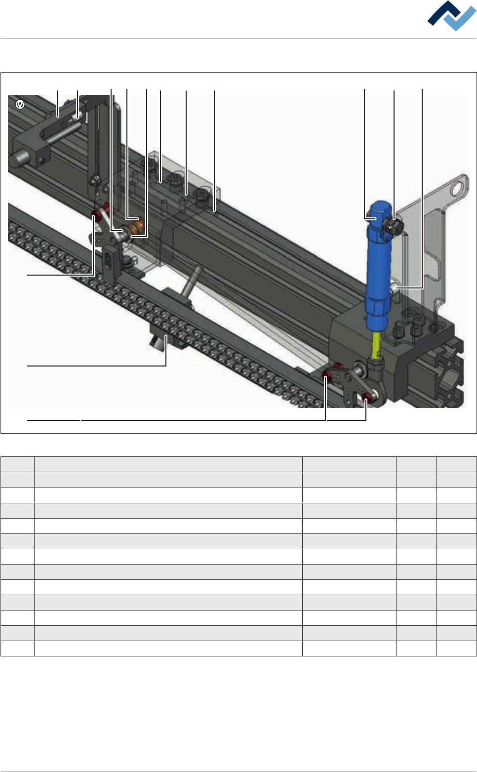
Fixed rail 1, (single track), view [W]
1 652 3 3 3 94 1011
8
7
7
Fig.262: EM113-339-10-00g
Pos Designation Item number A B
1 Support, Senor LK6, top * 170766 x
2 Pipe clamp DIN 72571 * 6ZT00211 x
3 Groove nut STM5 * 6ZIS049 x
4 Washer 8/14X0,5 DIN988 * 6SA08X0.50 x
5 Circlip A 8x0,8mm, DIN 471 * 6SER-A080471 x
6 Collar bush * 143513 x
7 Pan head screw M5 * 170207 x
8 Sensor holder, bottom, LK6 * 170750 x
9 Joint clip * 170367 x
10 Straight screwing M5, stainless stell * 97965 x
11 Cylinder, 2-acting Ø 16, stroke=20 Temp. resistant * 85950 x
* Only for option [Second stopper]
Ersa GmbH Operating Instructions_VF335_en|Rev. 14|30/11/2017 541/695
9|Spare and wear parts
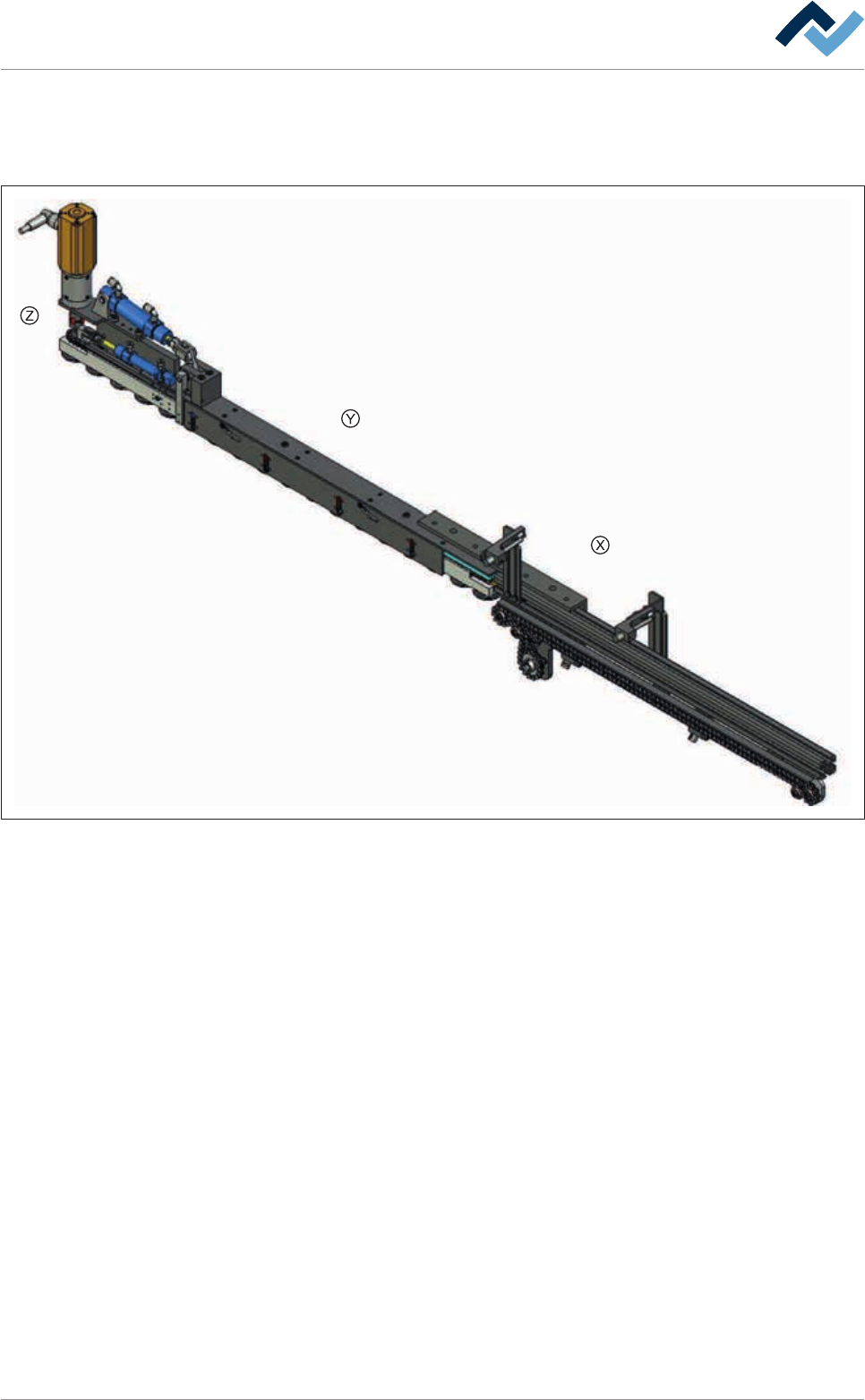
9.5.3.2 Fixed rail 2, (dual track)
Overview
Fig.263: EM113-30-00
Ersa GmbH Operating Instructions_VF335_en|Rev. 14|30/11/2017 542/695
9|Spare and wear parts
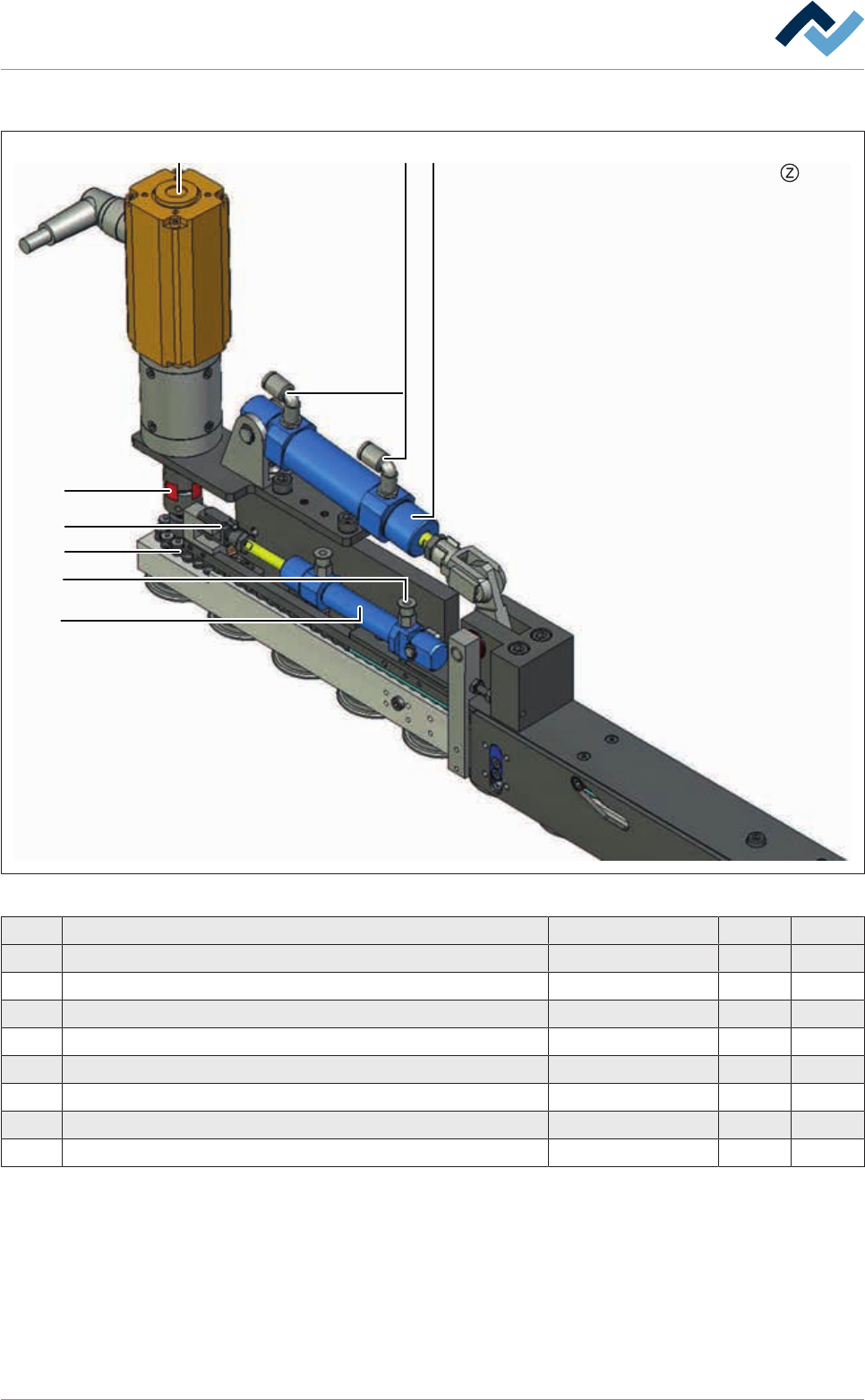
Fixed rail 2, (dual track), view [Z]
1
2
3
4
5
6
7
8
Fig.264: EM113-339-30-00a
Pos Designation Item number A B
1 Motor, Dunker, BG44x25SI/PLG S 32:1 117869 x
2 Coupling Ø 20x30 143509 x
3 Screw-in angle Ø 4 mm, 1,8" 126740 x
4 Cylinder, 2-acting Ø 20, stroke=25 Temp. resistant 43674 x
5 Straight plug connection M5, Ø 4 mm 126369 X
6 Cylinder, 2-acting Ø 12, stroke=25 mm 164014 X
7 Fork head G6x12 SL MBO 144383 X
8 Chain G52 05B-1 143514 x
Ersa GmbH Operating Instructions_VF335_en|Rev. 14|30/11/2017 543/695