Operating Instructions_VF335_en.pdf - 第254页
6|Function description 6.15.3 Prerequisites for installing a nozzle If you want to install a new nozzle in the Data table solder nozzle, the following prerequisites must be met: – The machine is in the [Maintenance mod…

6|Function description
– [Test tolerance plus] and [Test tolerance minus]: These two values define the
range in which the solder waves height test is to be performed. The minus tol-
erance thereby specifies how much of the test is due to be started before the
set offset. The plus tolerance specifies how far the test is due to be run beyond
the set offset to determine the new offset before the test process is stopped.
As minus and plus tolerance values, 700 and 2000 are respectively recommen-
ded.
– [Test offset max.]: This value limits the maximum control power. The offsets
identified in the solder wave height test cannot exceed this value.
Ersa GmbH Operating Instructions_VF335_en|Rev. 14|30/11/2017 253/695

6|Function description
6.15.3 Prerequisites for installing a nozzle
If you want to install a new nozzle in the Data table solder nozzle, the following
prerequisites must be met:
– The machine is in the [Maintenance mode] operating mode
– The solder pump has reached the operating condition [warm]
– The solder has reached the required set temperature
– The needle for the solder wave height test must be free of contamination
– The test position of the nozzle must be set correctly; the needle for the solder
wave height test must be located above the centre of the nozzle and show the
[Test distance [mm]] set in the nozzle table.
– The new nozzle must be clean and wettable
– The new nozzle must be used and warm
Ersa GmbH Operating Instructions_VF335_en|Rev. 14|30/11/2017 254/695
6|Function description
6.15.4 Tutorial: Installing a new solder nozzle
6.15.4.1 Entering a new nozzle into the nozzle table
ü To install a new solder nozzle in the nozzle table:
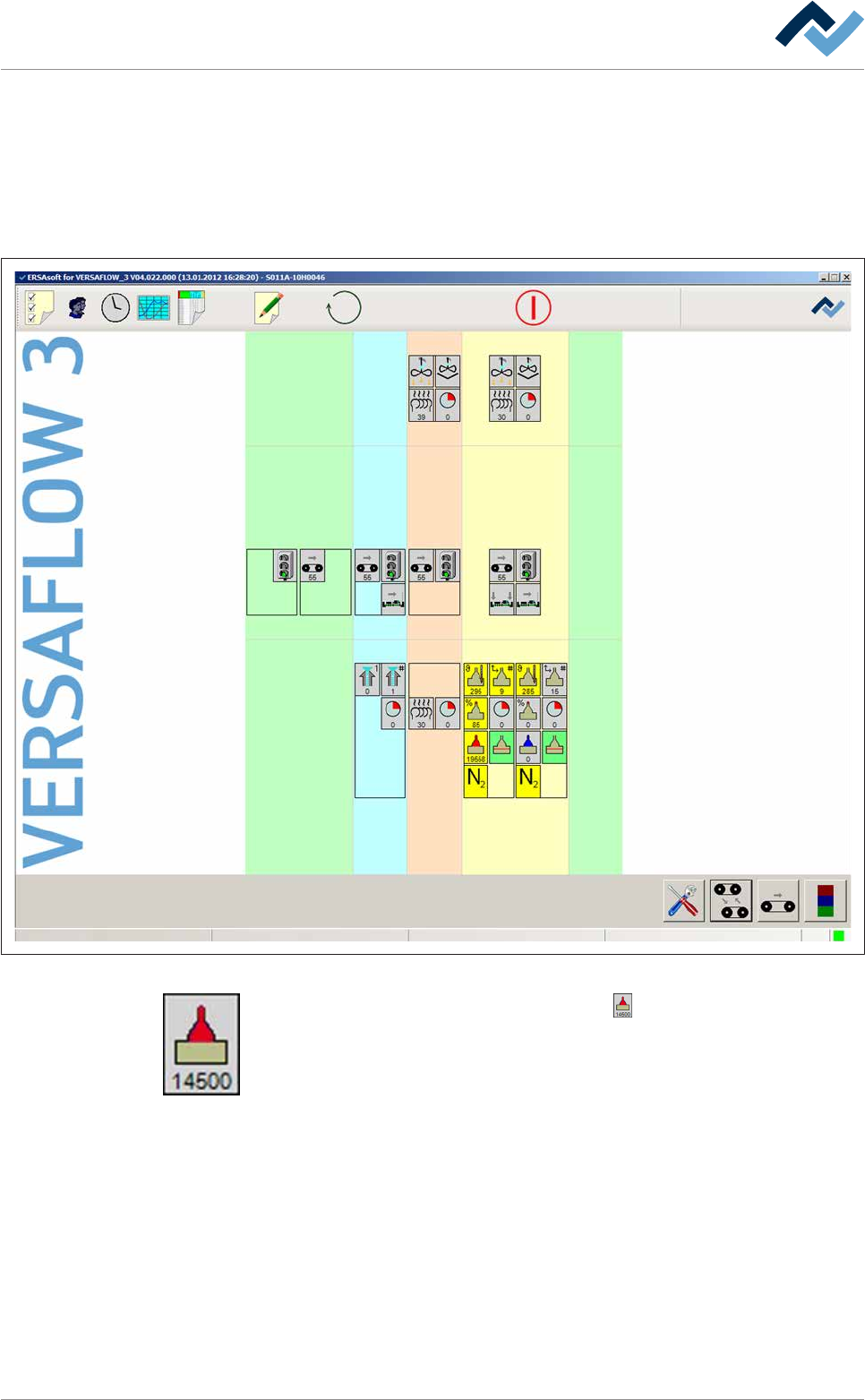
a) Open the start dialog.
Preheating Soldering module ExitInfeed Infeed unit
Solder pot
user: none
Flux unit
Maintenance mode
Fig.68: The start dialog of the control software:
b) In the [Soldering module] frame, click on the button.
ð If the machine is equipped with more than one solder pot, this button can
also be present more than once.
ð The [Soldering module] input dialog is opened:
Ersa GmbH Operating Instructions_VF335_en|Rev. 14|30/11/2017 255/695