Operating Instructions_VF335_en.pdf - 第630页
9|Spare and wear parts 1 2 3 4 Fig.345: EM113-85-00 Pos Description Item number A B 1 Camera, 1,3 Mega pixels, SXGA 1/2", CMOS 182569 x 2 Extension ring, C-mount, 10 mm 182573 x 3 Lens, Lensagon 182571 x 4 Counte…
9|Spare and wear parts
9.8.20 Fiducial recognition and deflection measurement
1 2634 5
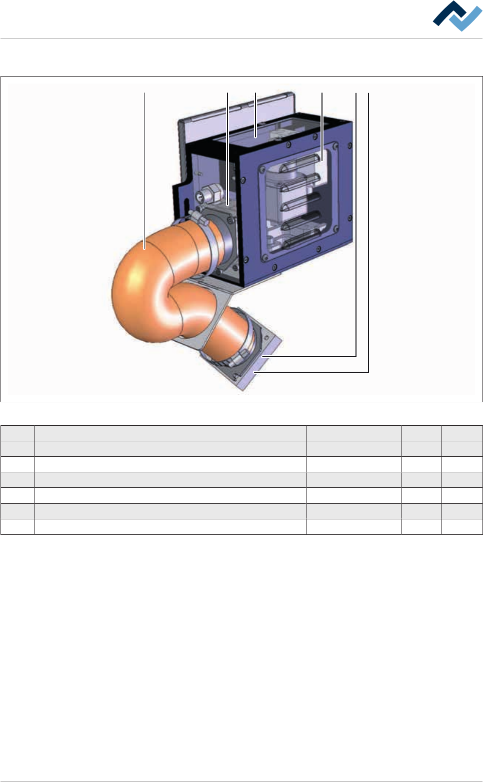
Fig.344: EM113-85-00a
Pos Description Item number A B
1 Cover glass, transparent 198509 x
2 Protective grid (Papst) 182901 x
3 Fan (Papst), 24V DC 202474 x
4 Hose, inside Ø 51 mm, temperature resistant up to 310° C 118351 x
5 Filter 236235 x
6 Laser distance sensor 200106 x
Ersa GmbH Operating Instructions_VF335_en|Rev. 14|30/11/2017 629/695
9|Spare and wear parts
123 4
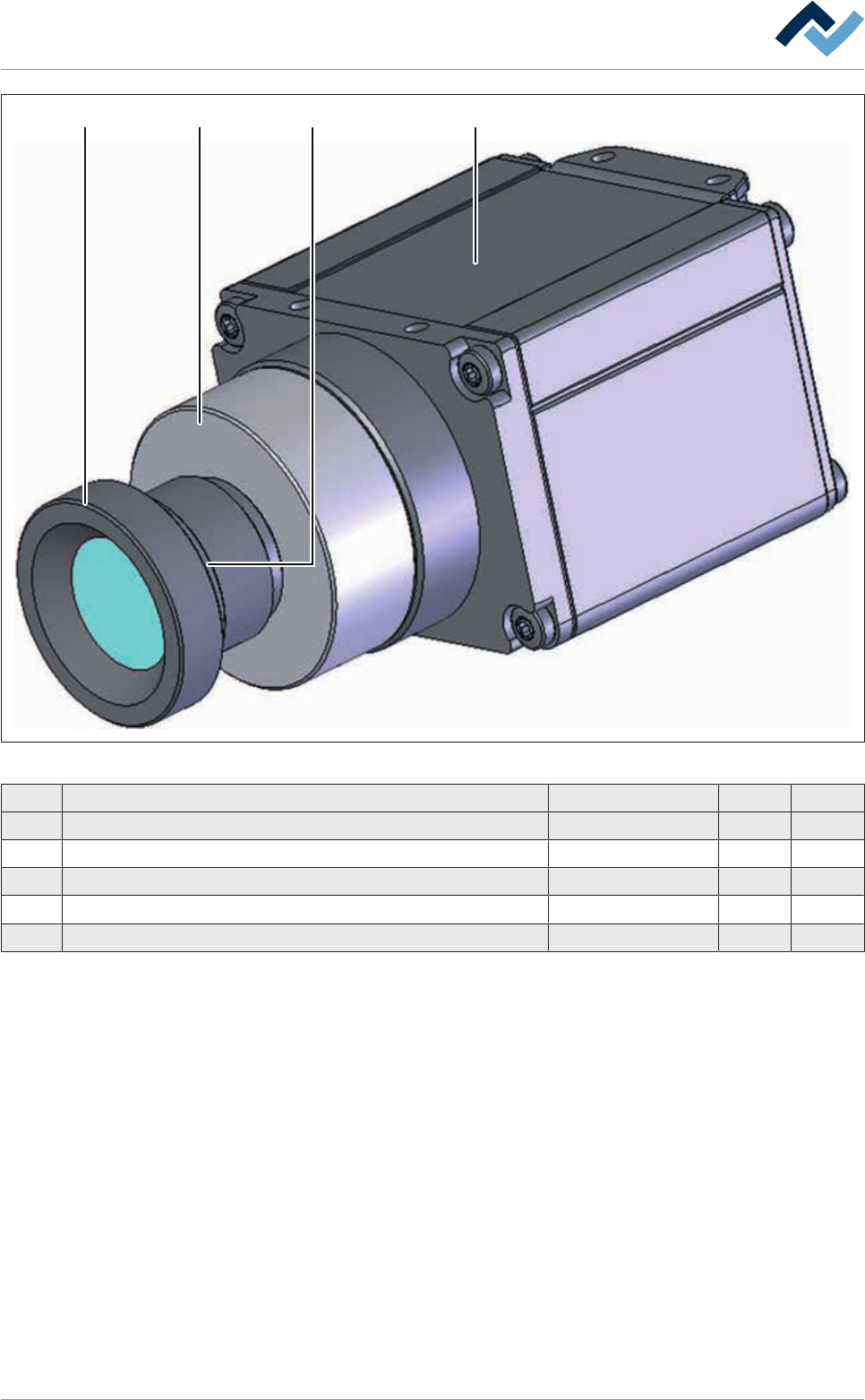
Fig.345: EM113-85-00
Pos Description Item number A B
1 Camera, 1,3 Mega pixels, SXGA 1/2", CMOS 182569 x
2 Extension ring, C-mount, 10 mm 182573 x
3 Lens, Lensagon 182571 x
4 Counter nut, Lensagon, M12 x 0,5 182574 x
5 Adaptor, C-mount / S-mount, Lensagon, wihout fig. 182572 x
Ersa GmbH Operating Instructions_VF335_en|Rev. 14|30/11/2017 630/695
9|Spare and wear parts
9.9 DIP_soldering units and options
9.9.1 DIP soldering module (multiwave) with paddle wheel pump
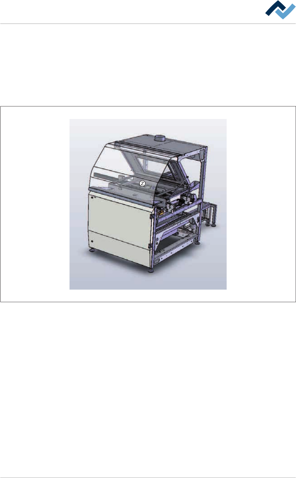
9.9.1.1 Gassing hood
Overview
Fig.346: EM58-21-01-00
Ersa GmbH Operating Instructions_VF335_en|Rev. 14|30/11/2017 631/695