Operating Instructions_VF335_en.pdf - 第662页
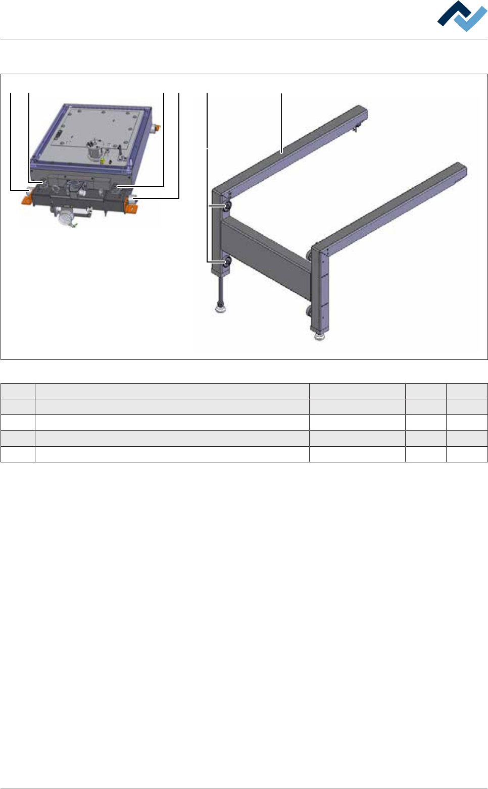
9|Spare and wear parts View [W] 1 4 2 1 2 3 Fig.376: EM131-61-00g Pos Description Item number A B 1 Adjusting screw 135733 x 2 Knurled roller Ø 50 mm 216492 x 3 Trolley 261146 x 4 Slilde roller 6LRO48-16-06 x Ersa Gmb…

9|Spare and wear parts
Pos Description Item number A B
4 Fixation screw M12 206598 x
5 Grease nipple, 90° 6SCHMNI6X1-90 x
6 Guide rail 254961 x
7 Y-Straight support 209052 x
8 Locking ring A30 6SER-A300471 x
9 Electric cylinder ETH080M10 260794 x
10 Cylindrical pin WC12.82.188 x
11 Tooth belt POWER GRIP HTD 6ZR0325-5M-15 x
Ersa GmbH Operating Instructions_VF335_en|Rev. 14|30/11/2017 661/695
9|Spare and wear parts
View [W]
1 42 1 2
3
Fig.376: EM131-61-00g
Pos Description Item number A B
1 Adjusting screw 135733 x
2 Knurled roller Ø 50 mm 216492 x
3 Trolley 261146 x
4 Slilde roller 6LRO48-16-06 x
Ersa GmbH Operating Instructions_VF335_en|Rev. 14|30/11/2017 662/695
9|Spare and wear parts
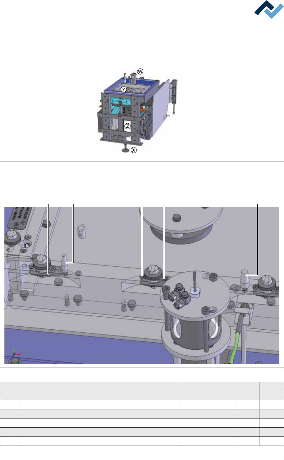
9.9.3.2 DIP soldering module (multiwave) XL pressure chamber and solder pot
Overview
Fig.377: EM131-61-00b
View [Y]
3 4 41 2
Fig.378: EM131-61-00c
Pos Description Item number A B
1 Fixing bolt, long, Ø = 8 mm 216359 x
2 Fixing bolt, long, Ø = 12 mm 216360 x
3 Bajonet cap, bottom part 139072 x
4 Countersunk screw 102588 x
5 Extraction tool for solder nozzles (without image) 12555 x
6 Box spanner SW13 (without illustration) 6ISK582005 x
Ersa GmbH Operating Instructions_VF335_en|Rev. 14|30/11/2017 663/695