Operating Instructions_VF335_en.pdf - 第424页
8|Service and maintenance b) To lift the replacement rack, push the lever (2) in direction (1) and move the bar up and down until you reach the desired height. c) To lower the replacement rack, push the lever (2) slowl…
8|Service and maintenance
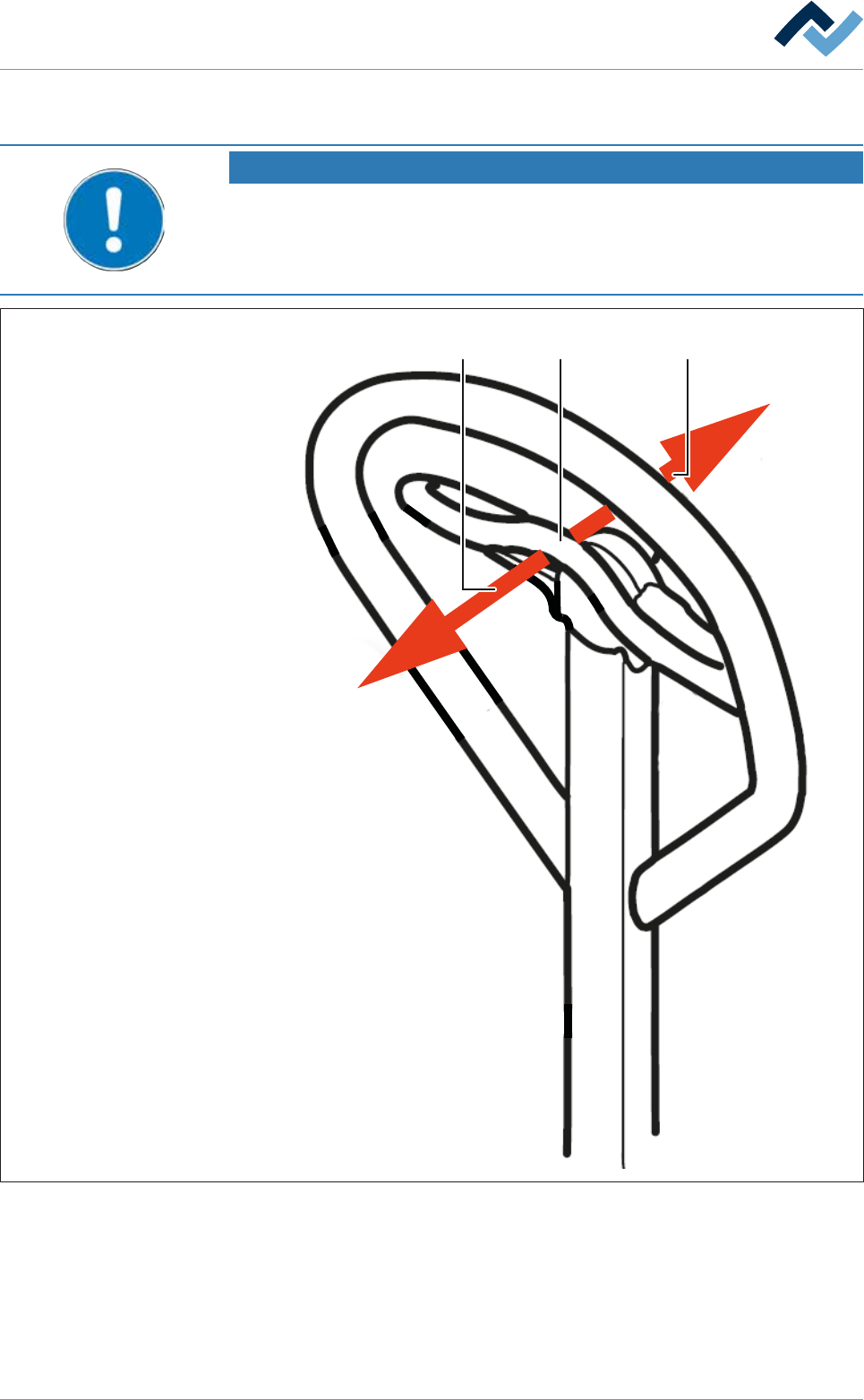
8.11.9.3 Operating the lifting cart with the replacement rack
NOTE
Supplementary documents
Before using the lifting cart for the first time, and in case you have any doubts about
its use, please read the corresponding manuals provided by the manufacturer to be-
come more acquainted with the relevant operating modes.
1 32
Fig.161: Operating the lifting cart
ü To operate the lifting cart.
ü The lifting cart is securely bolted to the replacement rack.
a) Before using the lifting cart for the first time, and in case you have any doubts
about its use, please read the corresponding manuals provided by the manu-
facturer.
Ersa GmbH Operating Instructions_VF335_en|Rev. 14|30/11/2017 423/695

8|Service and maintenance
b) To lift the replacement rack, push the lever (2) in direction (1) and move the
bar up and down until you reach the desired height.
c) To lower the replacement rack, push the lever (2) slowly in direction (3). The
replacement rack will be slowly lowered.
ð Always lower the replacement rack slowly and gently, in order to avoid any
damage to the replacement rack or the machine.
ð The process has now been completed.
Ersa GmbH Operating Instructions_VF335_en|Rev. 14|30/11/2017 424/695
8|Service and maintenance
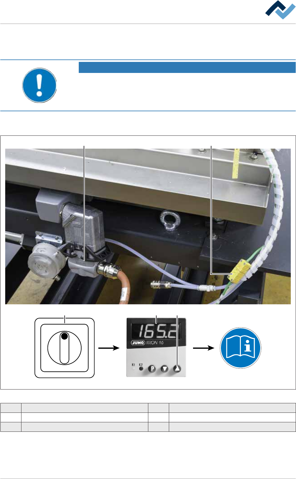
8.11.9.4 Connecting the cold solder pot to the (optional) heating station and
preheating it
NOTE
Heating up the solder before replacing the DIP solder pot
The solder can be heated up in the optional heating station before replacing the DIP
solder pot. Here it remains solid, but becomes hot. A safety switch in the heating sta-
tion prevents the solder from heating and liquefying any further.
ü To connect the cold solder pot to the heating station and preheat it:
ü You have donned the required protective clothing
1 2
Type 702041
I ON
0 OFF
3 4 5
Fig.162: Connecting the cold solder pot to the heating station
1 Plug-in connectors for solder pot heating 4 JUMO temperature controller
2 Thermocouple 5 Start button
3 Main switch
ü
Ersa GmbH Operating Instructions_VF335_en|Rev. 14|30/11/2017 425/695