Operating Instructions_VF335_en.pdf - 第498页
9|Spare and wear parts Z-axis excentric solder pot, y-variable 4 2 1 3 5 Fig.224: EM113-23-01-00b Pos Description Item number A B 1 Shock absorber 182130 x 2 Y-piece 103408 x 3 Angular-connector 100964 x 4 Reduction p…
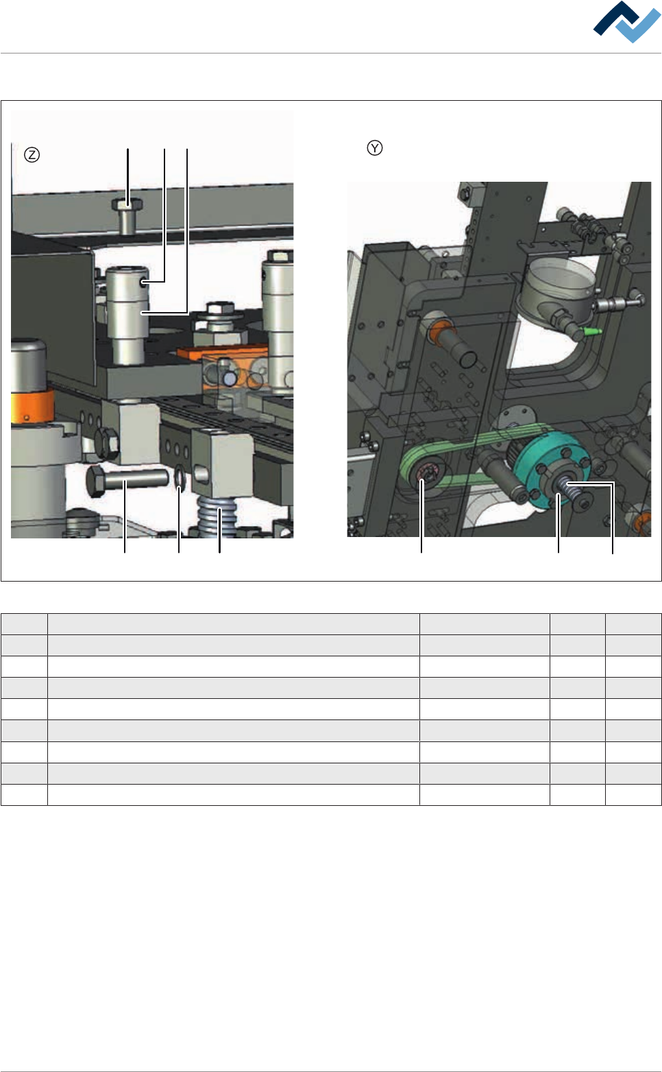
9|Spare and wear parts
Z-axis eccentric solder pot, y-variable, view [Y], [Z]
1 5
1 7 2
3
43
6
Fig.223: EM113-23-01-00a
Pos Description Item number A B
1 Hexagonal screw M6 6M06X025E0933 x
2 Tensioning kit 112207 x
3 Lifting spindle, complete * 209659 x
4 Ball nut * 184736 x
5 Positioning bolt * 192581 x
6 Set screw 6M04X004E0916 x
7 Locking ring 111800 x
* Cannot be shipped separately
Ersa GmbH Operating Instructions_VF335_en|Rev. 14|30/11/2017 497/695
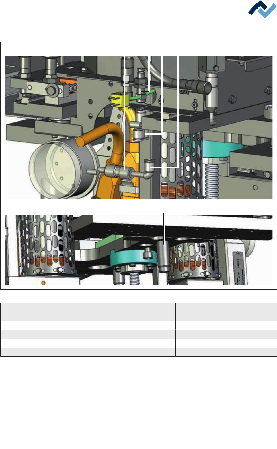
9|Spare and wear parts
Z-axis excentric solder pot, y-variable
4 2
1
35
Fig.224: EM113-23-01-00b
Pos Description Item number A B
1 Shock absorber 182130 x
2 Y-piece 103408 x
3 Angular-connector 100964 x
4 Reduction piece, straight, pluggable 100637 x
5 Connector, M10 x 1 182134 x
Ersa GmbH Operating Instructions_VF335_en|Rev. 14|30/11/2017 498/695
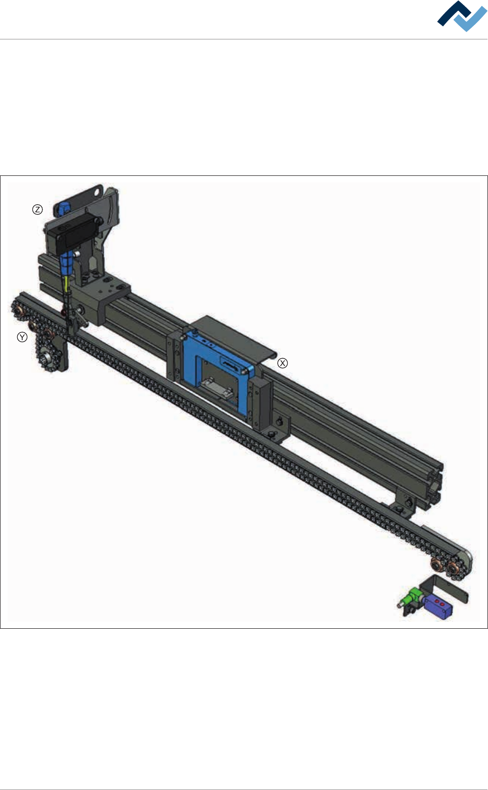
9|Spare and wear parts
9.5 Transport system
9.5.1 Fluxer unit conveyor system
9.5.1.1 Fixed rail 1, (single track)
Overview
Fig.225: EM113-333-10-00
Ersa GmbH Operating Instructions_VF335_en|Rev. 14|30/11/2017 499/695