Operating Instructions_VF335_en.pdf - 第567页
9|Spare and wear parts Fixed rail, DIP pump wheel, view [Y], [Z] 1 2 4 5 7 3 3 6 5 1 10 8 Fig.288: EM128-333-10-00a Pos Description Item number A B 1 Deflection roller Ø 21 mm 107607 x 2 Deflection roller, Ø 20 mm 211…
9|Spare and wear parts
9.5.4 DIP soldering unit conveyor system
9.5.4.1 Fixed rail, DIP pump wheel
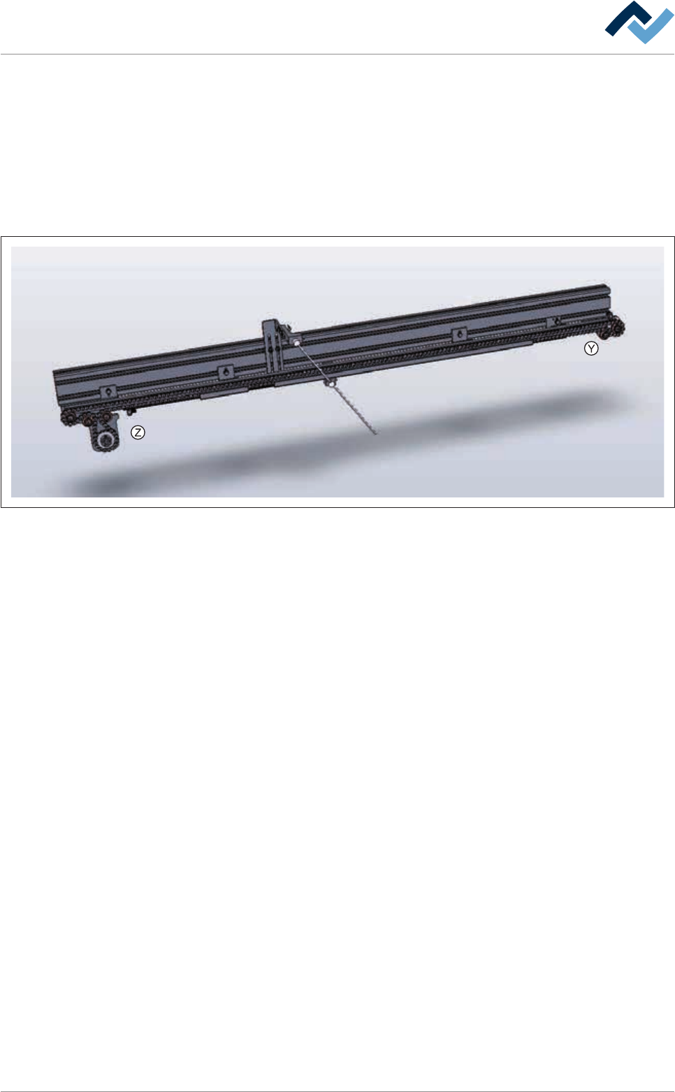
Overview
Fig.287: EM128-333-10-00
Ersa GmbH Operating Instructions_VF335_en|Rev. 14|30/11/2017 566/695
9|Spare and wear parts
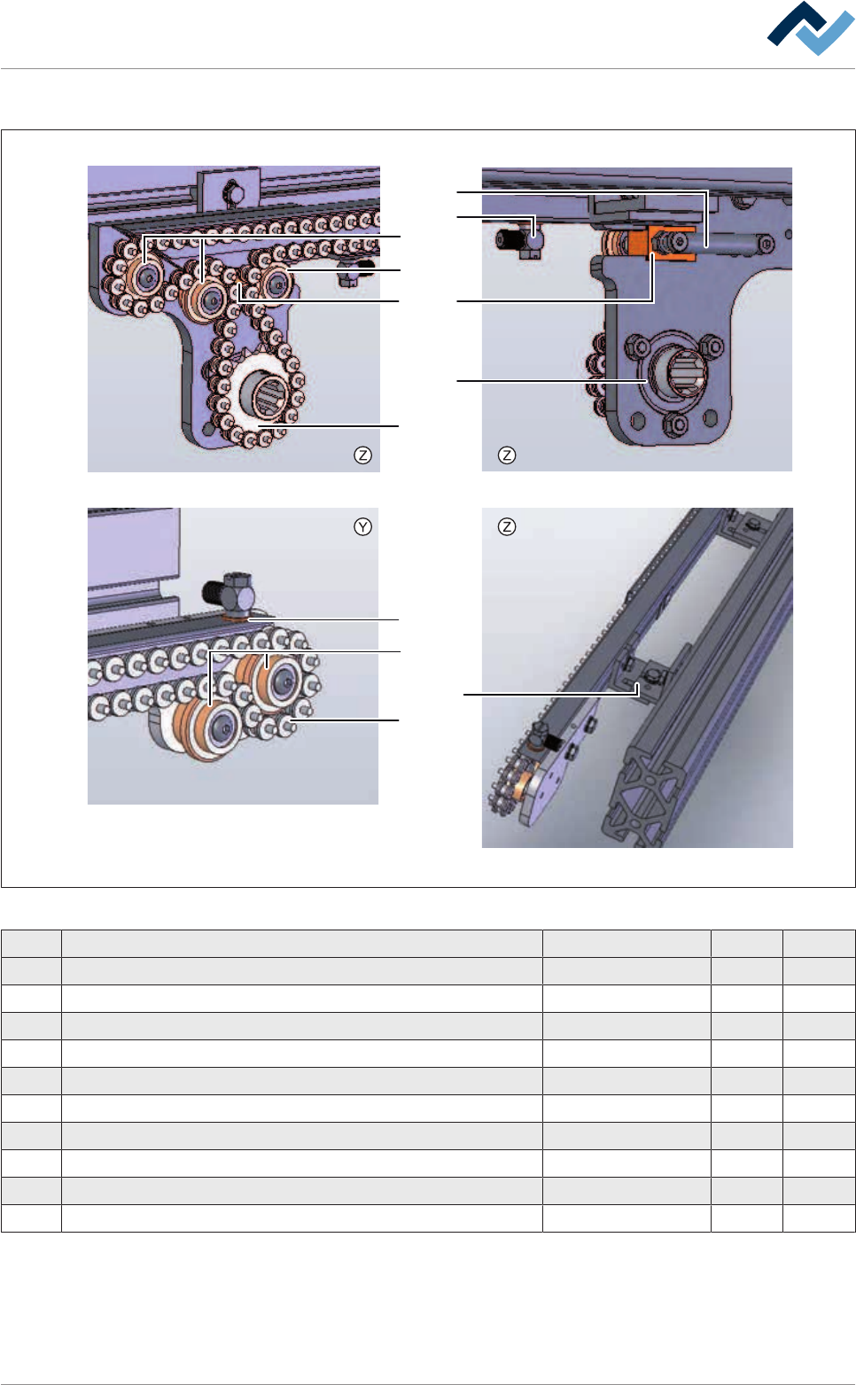
Fixed rail, DIP pump wheel, view [Y], [Z]
1
2
4
5
7
33
6
5
1
10
8
Fig.288: EM128-333-10-00a
Pos Description Item number A B
1 Deflection roller Ø 21 mm 107607 x
2 Deflection roller, Ø 20 mm 211062 x
3 Sliding piece (chain tensioner) 169520 x
4 Chain wheel Z=15 170047 x
5 Sealing ring, copper 153612 x
6 Spring 6FEDZ-094I x
7 Bearing 6LA619032RS x
8 Screw-in angle with cap nut 128566 x
9 Conveyor chain, 3 mm pins, bulk stock 208821 X
10 Chain joint 3 mm 208824 x
Ersa GmbH Operating Instructions_VF335_en|Rev. 14|30/11/2017 567/695
9|Spare and wear parts
9.5.4.2 Flexible rail, DIP pump wheel
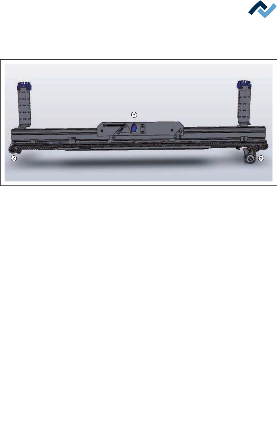
Overview
Fig.289: EM128-333-20-00
Ersa GmbH Operating Instructions_VF335_en|Rev. 14|30/11/2017 568/695