Operating Instructions_VF335_en.pdf - 第177页
6|Function description 6.9.8 Preheater module settings In this example, the preheater is provided with an upper compressed air heater and dynamic light emitters, which pre-heat the board from the bottom. The bottom pre…

6|Function description
In the [Congestion position] input fields, you can define a position for the nozzle,
which is always approached when the machine is somewhere congested with
boards.
Ersa GmbH Operating Instructions_VF335_en|Rev. 14|30/11/2017 176/695

6|Function description
6.9.8 Preheater module settings
In this example, the preheater is provided with an upper compressed air heater and
dynamic light emitters, which pre-heat the board from the bottom. The bottom
preheater cassette is divided into three segments.
Enabling the module
ü To enable the module:
a) In the [General soldering program data] dialog, activate the checkbox of the
module in level 1.
ð The module has now been enabled and is used in the soldering program.
Setting preheating temperature, preheating period
ü To set the preheating temperature and period:
a) In the [General soldering program data] dialog in level 2, click on the input
fields and enter the preheating temperature in [°C] and the prehating period in
[s].
ð The PCBs will thus be subjected from above to the preheating temperature for
the duration of [Preheating time].
Setting the conveyor speed
ü To set the conveyor speed:
a) In the [General soldering program data] dialog in level 3, click on the input field
of the conveyor section.
b) Enter the conveyor speed in [%] of the maximum possible speed value.
ð This is the speed at which the board is conveyed into the next module.
Segmented pre-heat unit: Enabling segments
ü To enable the segments of the bottom preheater:
a) Enable checkboxes in the [General soldering program data] dialog in level 6.
ð If a checkbox is enabled, the segment of the heater is used in the soldering pro-
gram.
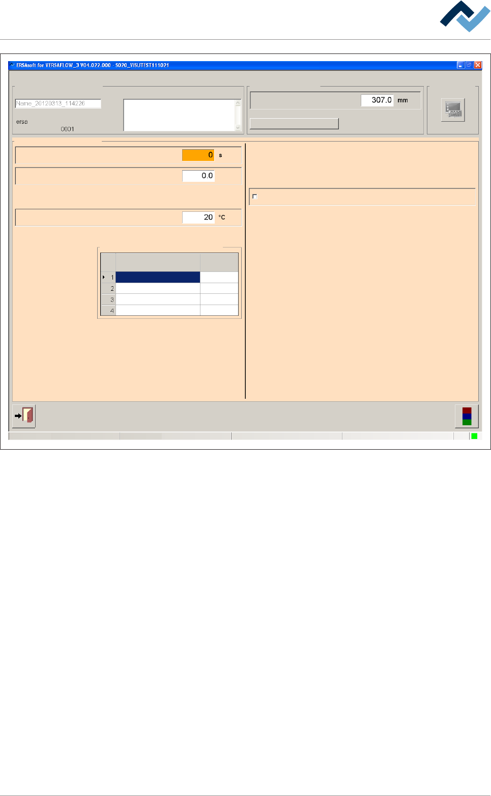
Performing extended settings in the [General additional data] dialog
ü To perform extended settings:
a) Open the [General soldering program data] dialog.
b) Below Level 6, click on the
button in the corresponding module.
Open the [General additional data] dialog. The yellow square provides information
about how often the dialog has already been opened.
Ersa GmbH Operating Instructions_VF335_en|Rev. 14|30/11/2017 177/695
6|Function description
user:
ersa
Soldering program editor General additional data
Program informations
Program name
Version:
Last modification by:
Infotext:
Conveyor
Conveyor width adjustment
Graphical data
Process time
Time until preheat repet.
General additional data
Number of preheat repet.
Table of power value
IR element graduation
Empty module always
Heating
Standby temperatureset value
Time
60
30
0
30
30
60
0
80
Maintenance mode
Fig.38: The [General additional data] dialog
Entering the waiting time between two heating cycles
ü [Time until preheat repet.], if the next module is not yet ready:
a) Click on the [Time until preheat repet.] input field and enter a time in [s].
ð The board is preheated. If the next module is not yet ready, the waiting time
expires. After this time, the heating cycle is repeated if a value greater than 0
has been entered in the [Number of preheat repet.] input field.
Entering the Number of preheat repet.
ü [Number of preheat repet.], if the next module is not yet ready:
a) Enter the [Number of preheat repet.] input field and the number of the pre-
heating repetitions.
ð If the next module is not yet ready, the preheating cycle is repeated according
to your entry. If subsequently the next module is still unavailable, a message is
displayed. If you have entered the value [0], the preheating cycle is not re-
peated.
Entering the Standby temperature
ü To enter the [Standby temperature] in [°C]:
a) Enter a value in [°C] in the input field.
Ersa GmbH Operating Instructions_VF335_en|Rev. 14|30/11/2017 178/695