Operating Instructions_VF335_en.pdf - 第188页
6|Function description 6.9.12.1 Fluxer unit data sets You can enter the nozzle target positions in the form of coordinates in the re- gisters. If you enter coordinates, these are always considered target coordinates st…
6|Function description
Dialog registers
All data is listed in table form, wherein each module is divided into several re-
gisters. The [Set] register contains the ascending numbering of the data sets.
Hiding a data set
ü To hide a data set so that it is not processed:
a) Activate the [Hide] checkbox.
ð If the checkbox is enabled, a checkmark appears. A data set marked in this way
is not processed.
Add a comment to a data set
ü To add a comment:
a) Enter an explanatory text into the [Description] edit field, for example [spray
path] or [solder point].
ð The comment has been added and is stored together with the soldering pro-
gram.
NOTE
When the
button is displayed in red
The button will turn red if necessary information is missing in the data sets. The relev-
ant cell is then highlighted.
NOTE
When a soldering program is incomplete
When a soldering program contains incomplete or useless entries, they are detected
by the control software. If the soldering program is saved, you receive an error mes-
sage. You can however save the soldering program; the incomplete soldering program
is then marked in the library with the
symbol. You cannot start an incomplete sol-
dering program. The incomplete soldering programs are not displayed in the [Program
selection] dialog.
Ersa GmbH Operating Instructions_VF335_en|Rev. 14|30/11/2017 187/695
6|Function description
6.9.12.1 Fluxer unit data sets
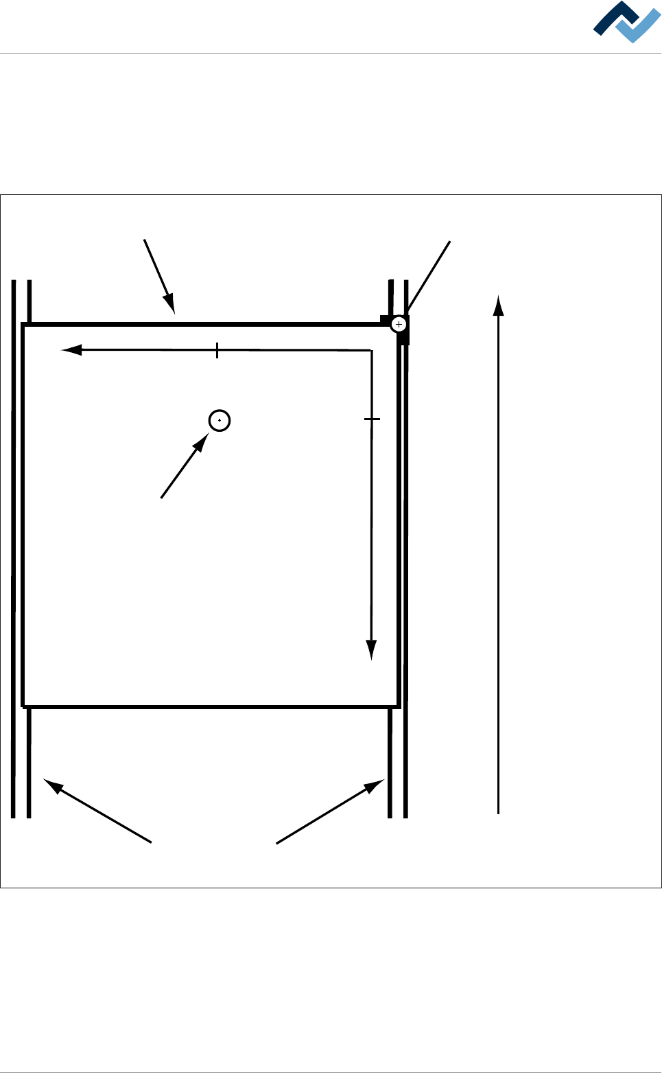
You can enter the nozzle target positions in the form of coordinates in the re-
gisters. If you enter coordinates, these are always considered target coordinates
starting from the barrier (= point of origin). You can enter the coordinates in [mm]
with an accuracy of 1/10mm via the keyboard. Please also consider the following
drawing:
Transfer direction
Blocker (= zero-point)Board
Conveyor
+Y
+X
29,5
13,5
Tip
Fig.42: Entering fluxer coordinates: In the example above, the nozzle is located at the end position [X = 13.5] / [Y = 29.5] (view from
above)
– The [Endposition X] register: Enter the end position of the nozzle in X direction
in [mm].
– The [Endposition Y] register: Enter the end position of the nozzle in Y direction
in [mm].
– The [Speed X/Y [mm/s]] register: Enter the travel speed of the nozzle in [mm/
s]. This is the speed at which the nozzle is moved to the X/Y end position.
Ersa GmbH Operating Instructions_VF335_en|Rev. 14|30/11/2017 188/695

6|Function description
– The [mode] register: Please specify which nozzles will be used for spraying. Use
the table below.
Ersa GmbH Operating Instructions_VF335_en|Rev. 14|30/11/2017 189/695