Operating Instructions_VF335_en.pdf - 第87页
4|Transport, installation, storage, disposal 4.11.7 Connection to the exhaust air monitoring system Potential-free contact for switching on the local exhaust air system The machine provides a potential-free contact (no…
4|Transport, installation, storage, disposal
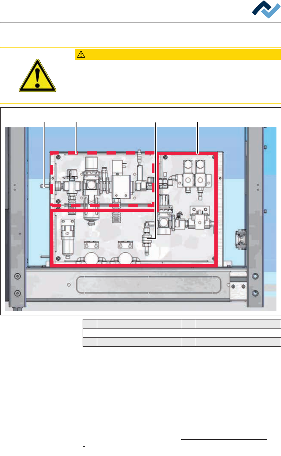
4.11.6 Connection to an inert gas supply unit
CAUTION
Pressurized machine parts!
Personal or material damage due to pressurized machine parts or unexpected move-
ment of the mechanism!
a) Such work may therefore only be performed by properly trained and qualified
personnel!
1 243
1 Compressed air supply 4 Nitrogen connection
2 Nitrogen supply
3 Compressed air connection
ü Connect the inert gas supply:
ü The inert gas supply is located behind the casing panel in the flux storage room.
ü the protective gas supply provided by the customer is switched off.
a) Read the provided connection diagrams.
b) Connect the on-site inert gas supply to the supplied quick coupling, and secure
with a hose clamp.
c) Connect the quick coupling to the connection (4).
d) Switch on the protective gas supply provided by the customer.
ð The process has now been completed.
With respect to this, please read Chapter Protective gas technology (nitrogen)
[}26].
Ersa GmbH Operating Instructions_VF335_en|Rev. 14|30/11/2017 86/695
4|Transport, installation, storage, disposal
4.11.7 Connection to the exhaust air monitoring system
Potential-free contact for switching on the local exhaust air system
The machine provides a potential-free contact (normally open contact, loading ca-
pacity 24V / 100mA) to switch on the local exhaust air system. As soon as the ma-
chine control system is ready, this contact is closed.
ü To connect the potential-free contact:
a) read the wiring diagrams provided.
b) Connect the lines required.
c) Test the correct functioning.
ð The process has now been completed.
4.12 Storage
CAUTION
Material damage is possible!
a) Protect the machine from weather conditions (moisture, humidity, sea air, fog)! If
required, provide the machine with dehumidifying agent and air tight packaging.
ü Environmental conditions
a) Allowed storage temperature: 10°C...35°C
b) Allowed relative humidity in storage: 20 .. 95% non-condensing, relative hu-
midity
Ersa GmbH Operating Instructions_VF335_en|Rev. 14|30/11/2017 87/695

4|Transport, installation, storage, disposal
4.13 Disposal
CAUTION
Disposal
ü Solder waste is hazardous waste and must not be disposed of together with do-
mestic waste.
a) Provide safe and environmentally friendly disposal of packaging materials!
b) Make sure that all process materials and replacement parts are disposed of in a
safe and environmentally friendly way!
In accordance with Directive 2008/98/EC and Directive 2002/96/EC on waste elec-
trical and electronic equipment, we recommend the following procedure:
ü Preparing the machine for disposal:
a) Having all the machine supply equipment separated by qualified personnel:
ð Power supply
ð Suction:
ð Pneumatics, water and nitrogen supply
ð Computer network
b) Drain all liquids and collect them separately in suitable containers:
ð Cooling water (containing antifreeze)
ð Flux material
ð Condensates
ð Hydraulic oil, lubricating oil
ð Only when all these operations have been carried out, can the disposal of the
machine be started.
ü If the user is not in a position to carry out proper scrapping:
a) Please contact a certified disposal company.
Ersa GmbH Operating Instructions_VF335_en|Rev. 14|30/11/2017 88/695