Operating Instructions_VF335_en.pdf - 第31页
2|Technical data Designation Board edge support (mm) 1 3 Maximum height of components on the PCB (mm) 120 Maximum height of the parts under the PCB (mm) 2 30 Recommended nozzle distance from the board (mm) 1…1.5 Positi…
2|Technical data
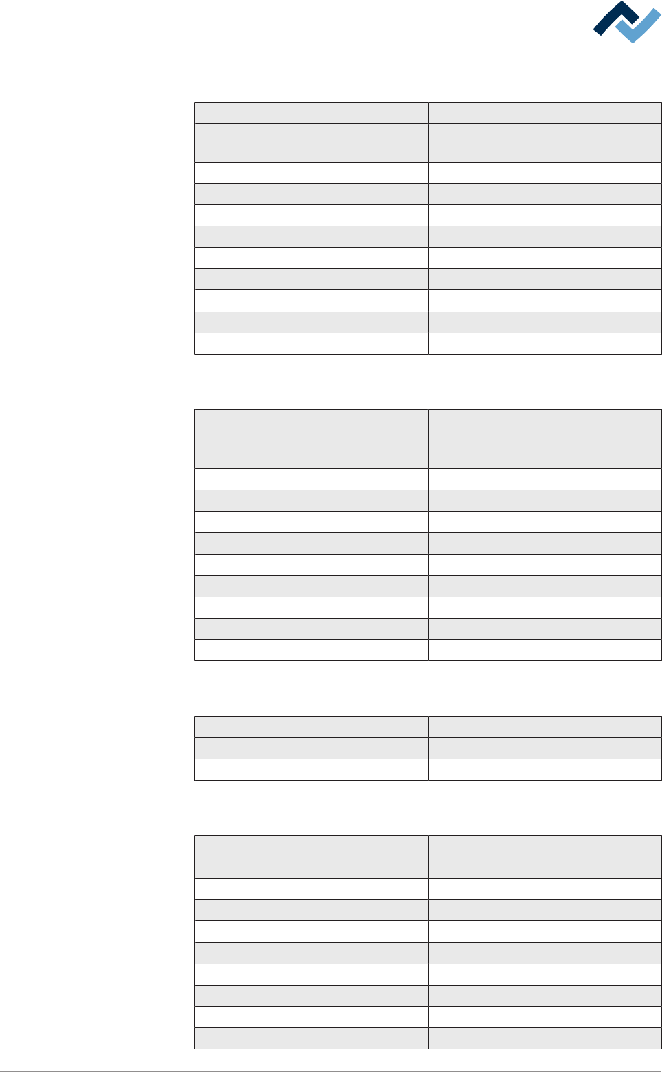
2.2.7 DIP soldering module (standard ) with induction pump
Description
Module type DIP soldering module with induction
pump
Heating output (kW) 6.05
Solder content approx. (kg) 230
Heat-up time to 280°C (min) 210
Maximum solder temperature (°C) 300
Maximum PCB height (mm) 450
Maximum PCB width (mm) 350
Positioning speed Z axis (mm/sec) 20
Positioning accuracy ± 0.25
Handling system Motor-driven by threaded spindle
2.2.8 DIP soldering module XL with induction pump
Description
Module type DIP soldering module with induction
pump
Heating output (kW) 6.05
Solder content approx. (kg) 300
Heat-up time to 280°C (min) 240
Maximum solder temperature (°C) 300
Maximum PCB height (mm) 500
Maximum PCB width (mm) 360
Positioning speed Z axis (mm/sec) 20
Positioning accuracy ± 0.25
Handling system Motor-driven by threaded spindle
2.2.9 Solder supply: DIP soldering unit
Designation
Solder bar dimensions (mm) 255 x 55 x 40
Maximum weight (kg) 8.7
2.2.10 Single-track conveyor system
Designation
Type Frameless conveyor system
Transport system Segmented single conveyors
Conveyor speed (m/min) 0.2…10
Standard conveyor width (mm) 60…406
Type of conveyor width adjustment Motorized, front fixed rail conveyor
Conveyor angle (°), not adjustable 0
Board length (mm) 120…508
Board width (mm) 63.5…406
Max. board weight (kg) 8
Ersa GmbH Operating Instructions_VF335_en|Rev. 14|30/11/2017 30/695

2|Technical data
Designation
Board edge support (mm)
1
3
Maximum height of components on the
PCB (mm)
120
Maximum height of the parts under the
PCB (mm)
2
30
Recommended nozzle distance from the
board (mm)
1…1.5
Positioning accuracy of the board (mm) ± 0.2
1
In the marginal area of 3 mm, no superstructures and substructures may be
present!
2
Optionally, they are possible up to 60 mm.
Ersa GmbH Operating Instructions_VF335_en|Rev. 14|30/11/2017 31/695
2|Technical data
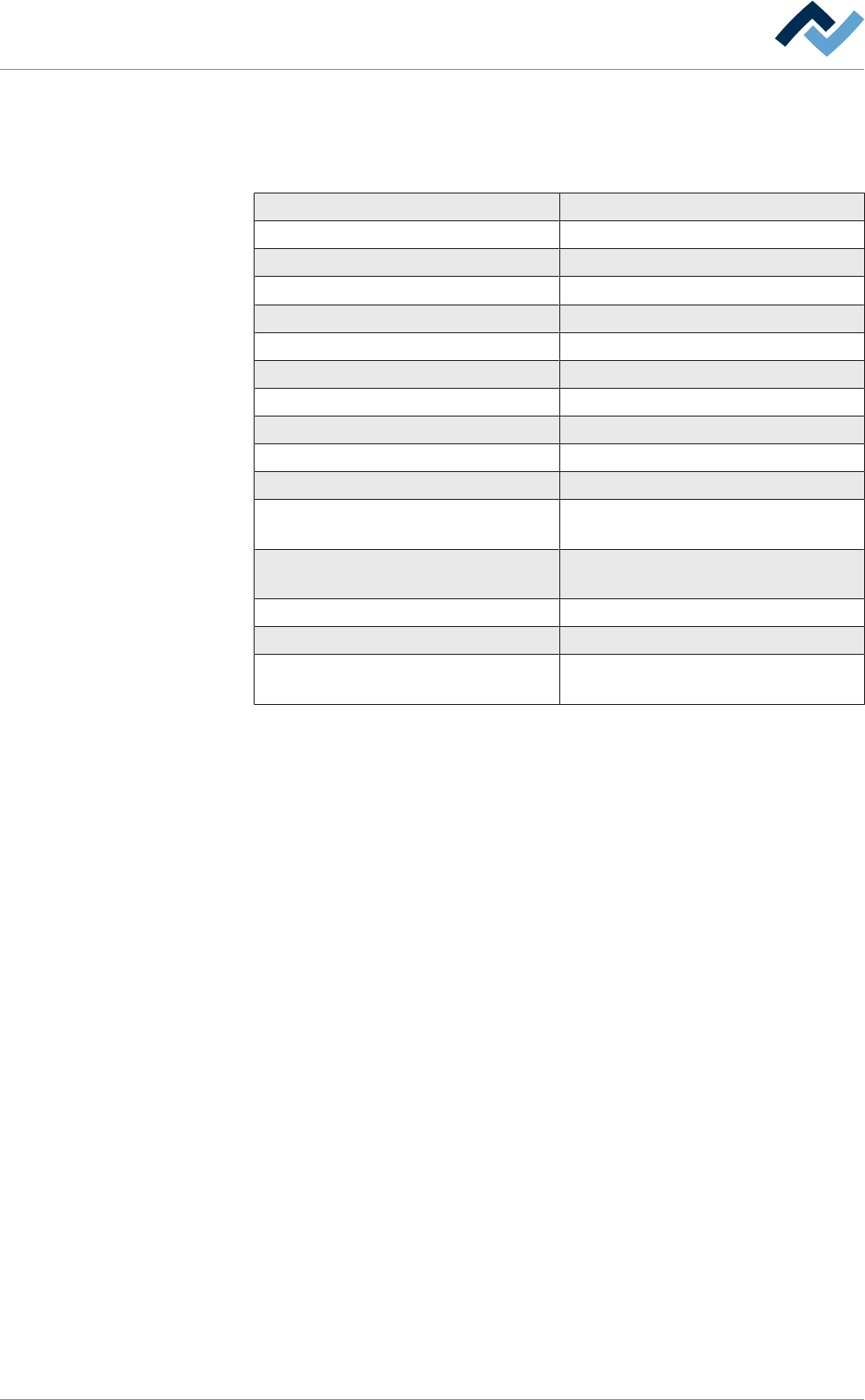
2.2.11 Available optionals
X = Standard
O = Optional
Automatic solder feeder O
Solder wave height measurement X
Segmented conveyor X
Process monitoring with camera O
Network capability O
Remote maintenance O
Centre support in the soldering module O
Soldering material hold-down system O
Top compressed air heater O
Code reader (barcodes) O
Code reader (matrix) O
Bottom preheater, dynamic IR emitter
cassette
X
Door and window interlocking system
(process reliability)
O
CAD assistant O
DIP replacement solder pot O
Heating station for DIP replacement
solder pot
O
Ersa GmbH Operating Instructions_VF335_en|Rev. 14|30/11/2017 32/695