Operating Instructions_VF335_en.pdf - 第187页
6|Function description Dialog registers All data is listed in table form, wherein each module is divided into several re- gisters. The [Set] register contains the ascending numbering of the data sets. Hiding a data set…
6|Function description
6.9.12 Working with data sets
The [Set data] dialog contains all the necessary data for the manufacturing process.
Creating data sets in the [Set data] dialog
ü To create data sets:
a) Open the [General soldering program data] dialog.
b) Click on the
button in the corresponding module below level 6.
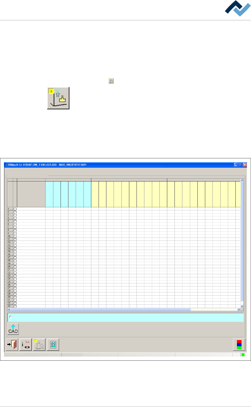
Open the [Set data] dialog. In this dialog, you can create your soldering program. It
contains target coordinates for fluxer and soldering modules, travel speeds and in-
formation regarding the solder wave height. The yellow square provides informa-
tion about how often the dialog has already been opened.
Data sets
A soldering program can contain an unlimited number of data sets. If the number
of data sets exceeds 15, a new data set is created automatically at the bottom end
of the table. Use the scroll bar at the right edge of the window to scroll through the
window and view all data sets.
Soldering program editor
user:
ersa
Maintenance mode
Set data
Set data
Set
Hide
Description
Endposition X [mm]
Endposition Y [mm]
Speed X/Y [mm/s]
mode
Spray amount [%]
Spray time [s]
Flux unit Soldering unit 1
Z while moving [mm]
Endposition X [mm]
Endposition Y [mm]
Speed X/Y [mm/s]
Endposition Z [mm]
Speed Z [mm/s]
Wave height [%]
Soldering time [s]
Lower value [%]
Lowering time [s]
Soldering unit 2
Z while moving [mm]
Endposition X [mm]
Endposition Y [mm]
Speed X/Y [mm/s]
Endposition Z [mm]
Speed Z [mm/s]
Wave height [%]
Soldering time [s]
Lower value [%]
Lowering time [s]
Fluxer coordinates relate to nozzle 1
Fig.41: Data sets with individual registers
Ersa GmbH Operating Instructions_VF335_en|Rev. 14|30/11/2017 186/695
6|Function description
Dialog registers
All data is listed in table form, wherein each module is divided into several re-
gisters. The [Set] register contains the ascending numbering of the data sets.
Hiding a data set
ü To hide a data set so that it is not processed:
a) Activate the [Hide] checkbox.
ð If the checkbox is enabled, a checkmark appears. A data set marked in this way
is not processed.
Add a comment to a data set
ü To add a comment:
a) Enter an explanatory text into the [Description] edit field, for example [spray
path] or [solder point].
ð The comment has been added and is stored together with the soldering pro-
gram.
NOTE
When the
button is displayed in red
The button will turn red if necessary information is missing in the data sets. The relev-
ant cell is then highlighted.
NOTE
When a soldering program is incomplete
When a soldering program contains incomplete or useless entries, they are detected
by the control software. If the soldering program is saved, you receive an error mes-
sage. You can however save the soldering program; the incomplete soldering program
is then marked in the library with the
symbol. You cannot start an incomplete sol-
dering program. The incomplete soldering programs are not displayed in the [Program
selection] dialog.
Ersa GmbH Operating Instructions_VF335_en|Rev. 14|30/11/2017 187/695
6|Function description
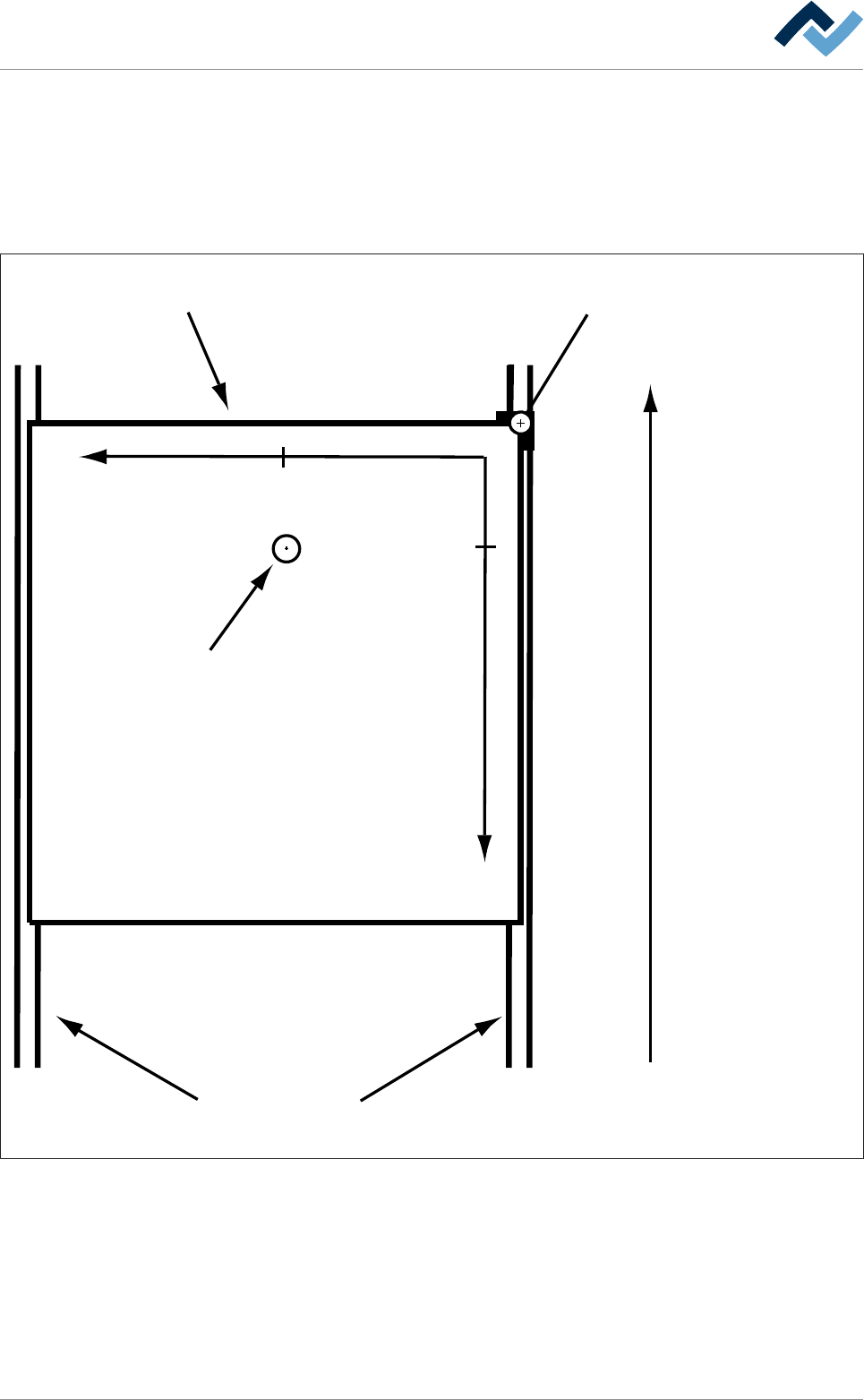
6.9.12.1 Fluxer unit data sets
You can enter the nozzle target positions in the form of coordinates in the re-
gisters. If you enter coordinates, these are always considered target coordinates
starting from the barrier (= point of origin). You can enter the coordinates in [mm]
with an accuracy of 1/10mm via the keyboard. Please also consider the following
drawing:
Transfer direction
Blocker (= zero-point)Board
Conveyor
+Y
+X
29,5
13,5
Tip
Fig.42: Entering fluxer coordinates: In the example above, the nozzle is located at the end position [X = 13.5] / [Y = 29.5] (view from
above)
– The [Endposition X] register: Enter the end position of the nozzle in X direction
in [mm].
– The [Endposition Y] register: Enter the end position of the nozzle in Y direction
in [mm].
– The [Speed X/Y [mm/s]] register: Enter the travel speed of the nozzle in [mm/
s]. This is the speed at which the nozzle is moved to the X/Y end position.
Ersa GmbH Operating Instructions_VF335_en|Rev. 14|30/11/2017 188/695