Operating Instructions_VF335_en.pdf - 第644页
9|Spare and wear parts Pos Description Item number A B 4 Fixation screw M12 206598 x 5 Grease nipple, 90° 6SCHMNI6X1-90 x 6 Guide rail 254961 x 7 Y-Straight support 209052 x 8 Locking ring A30 6SER-A300471 x 9 Electric…
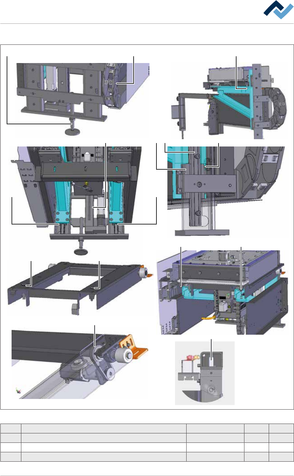
9|Spare and wear parts
View [X]
1 2
33
88
3 6 59
4
77
10
11
Fig.359: EM131-61-00a
Pos Description Item number A B
1 Adjusting foot 256979 x
2 Energy chain 208191 x
3 Guide wagon 206599 x
Ersa GmbH Operating Instructions_VF335_en|Rev. 14|30/11/2017 643/695

9|Spare and wear parts
Pos Description Item number A B
4 Fixation screw M12 206598 x
5 Grease nipple, 90° 6SCHMNI6X1-90 x
6 Guide rail 254961 x
7 Y-Straight support 209052 x
8 Locking ring A30 6SER-A300471 x
9 Electric cylinder, stroke 170 206369 x
10 Cylindrical pin WC12.82.188 x
11 Tooth belt POWER GRIP HTD 6ZR0325-5M-15 x
Ersa GmbH Operating Instructions_VF335_en|Rev. 14|30/11/2017 644/695
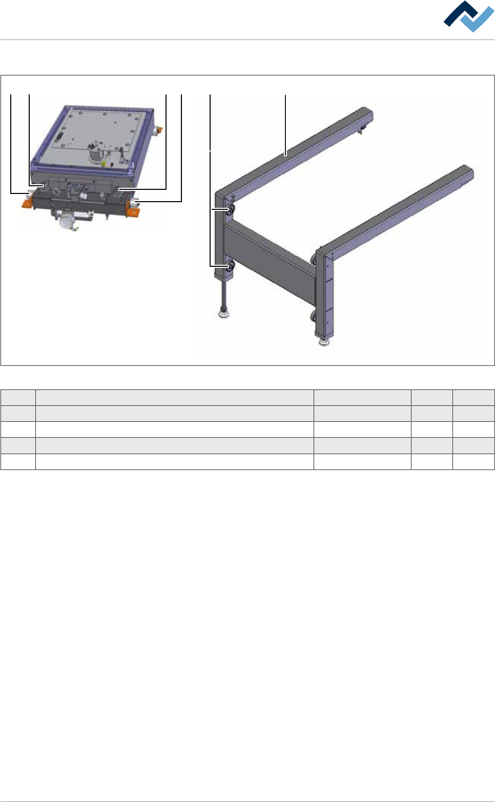
9|Spare and wear parts
View [W]
1 42 1 2
3
Fig.360: EM131-61-00g
Pos Description Item number A B
1 Adjusting screw 135733 x
2 Knurled roller Ø 50 mm 216492 x
3 Trolley 209306 x
4 Slilde roller 6LRO48-16-06 x
Ersa GmbH Operating Instructions_VF335_en|Rev. 14|30/11/2017 645/695