Operating Instructions_VF335_en.pdf - 第220页
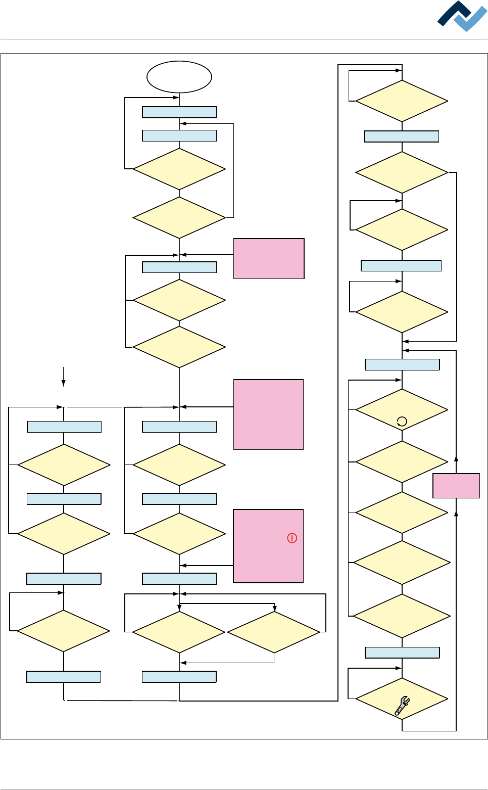
6|Function description 6.12.1 Changing the operating mode The most important operating modes of the machine are displayed as rectangles in the flowchart. The text within these rectangles is always displayed in the stat…
6|Function description
Within the Option
[blue RESET button]
Main switch
ON
Electronic OFF
Electronic Init
Power OFF
Voltage supply OKVoltage supply OK
Check emergency-stopCheck emergency-stop
Movement OFF Movement OFF
Maintenance mode
Button
[Movement ON] pressed?
No
NoNo
No
No
No
Yes
Yes
Yes
Referencing off all
servo axes OK?
No PCB inside the
machine?
No
Yes
NO message is
pending which prevents the
change to [Automatic]
No
Yes
Has the operator
selected a soldering program?
No
Yes
Yes
No
Yes
Yes
Yes
Has a pre-activate
point been reached, e.g.
[Heating]?
No
Yes
Weekly timer
in ON phase?
Has the blue
RESET button been
pressed?
No
Yes
Yes
Emergency-off OK?
No
Emergency-off OK?
No
Yes
Exhaust air OK?
The following condition also
directly results in
[Voltage supply OK]:
- Emergency-off pushed
OR emergency-off
error
- Weekly timer in OFF
phase AND machine
empty
No error for
[Electronic OFF]
pending?
CAN initializ
ing AND PLC
initializing OK?
Button [Automatic]
pressed?
No
No
Movement ON
Button
[Movement ON] pressed?
No
Yes
Movement ON
Machine Init
Referencing servo axes
Internal: PLC OK?
Referencing
Servo axes OK?
No
Yes
Yes
Yes
No
Yes
Has the
operator started the
referencing of the Servo
axes?
No
Are servo axes
availabe?
No
Supply
voltage OK?
Button
[Maintenance] pressed?
The following condition also
directly results in [Power Off]:
- The
visualization
software version is
outdated.
The following condition also
directly results in
[Movement OFF]:
- The [Movement Off]
key has been pushed
- An error is pending which
results in [Movement off];
e.g. optional CAN device
not configured
The dialog
[...................]
is displayed
Automatic
Flussdiagramm: Die blauen Rechtecke definieren die Betriebsarten der Maschine. Diese Betriebsarten
werden auch in der Statusleiste der Bedienoberfläche angezeigt.
Ersa GmbH Operating Instructions_VF335_en|Rev. 14|30/11/2017 219/695
6|Function description
6.12.1 Changing the operating mode
The most important operating modes of the machine are displayed as rectangles in
the flowchart. The text within these rectangles is always displayed in the status bar
of the start dialogue. There you can always read the current operating mode.
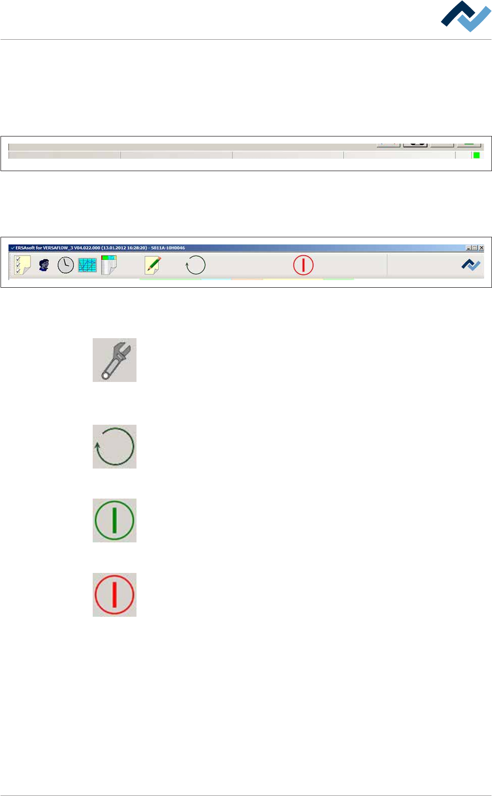
The status bar can be found at the lower edge of the screen:
user: none Automatic mode Library Soldering program
Fig.52: The status bar displays the currently logged in user and the current operating mode of the machine. In addition, in auto-
matic mode the library and the currently active soldering program are displayed.
The buttons for the operating modes are visible in the top toolbar of the start dia-
logue.
Preheating Soldering module ExitInfeed Infeed unit
Solder pot
user: none maintenance mode
Flux unit
Fig.53: Top toolbar
If the machine is in the [Automatic mode] operating mode:
This button is only visible in the [Automatic mode] operating mode. By clicking on
this button, you can stop an active soldering program and set the machine to the
[Maintenance mode]operating mode.
If the machine is in the [Maintenance mode] operating mode:
Click on this button to change the operating mode of the machine or select a sol-
dering program.
If the machine is in the [Movement off] operating mode:
If the green symbol is displayed, the machine is in the [Movement off] operating
mode: Click on this button to switch to the [Maintenance mode] operating mode:
If the machine is in the [Maintenance mode] operating mode:
When the red symbol appears, the machine is in the [Maintenance mode] operat-
ing mode. By clicking on this button, you can switch to the [Movement off] operat-
ing mode.
Ersa GmbH Operating Instructions_VF335_en|Rev. 14|30/11/2017 220/695
6|Function description
6.13 Soldering report and operating data
This function allows a precise logging and documentation of the entire production
process. You can monitor and export the data of a manufacturing batch. You can
have a separate process data file generated automatically for each PCB of a series.
Opening the dialogue
ü Opening the [Soldering report and operating data] edit dialogue:
a) on the top toolbar of the start dialogue, click on the
button.
ð When the [Password] edit dialogue is displayed:
b) enter user name and correct password.
ð After entering [User name] and [Password:] correctly, the [Soldering report and
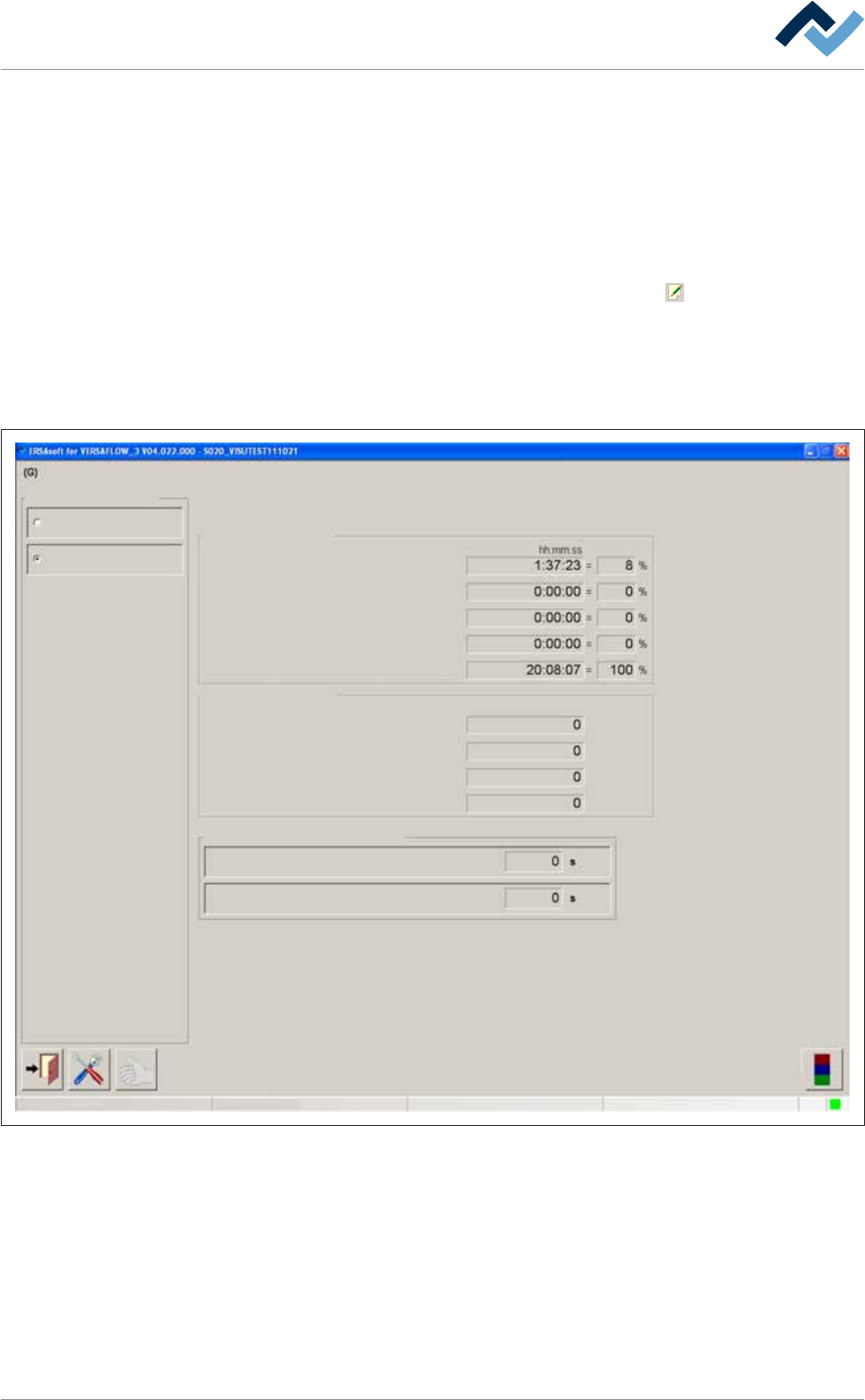
operating data] edit dialogue is displayed:
User ersa Maintenance mode
Soldering report and operating data
Operating data
Operating data
Operating data
Soldering report
Running times
Time in maintenance mode
Time in production mode
Waiting time while production mode
Waiting time congestion successor
Total time
Number of boards
Currently in machine
Total boards
Produced boards
Defective boards
Waiting time while production mode
Waiting time congestion successor
(N-1)
(N+1)
(N-1)
(N+1)
Selection
Delay time to counter start
Fig.54: The input dialog [Soldering report and operating data]. By enabling the radio buttons top left, you can open the corres-
ponding dialogs.
Ersa GmbH Operating Instructions_VF335_en|Rev. 14|30/11/2017 221/695