Operating Instructions_VF335_en.pdf - 第124页
6|Function description 6.2.2 Signal lamp 1 2 3 4 5 1 Horn: The horn sounds when a message appears for a set period of time. This function can be disabled. 2 Red: Emergency; dangerous condition, abnormal condition, immi…
6|Function description
6.2 Machine operation
The machine is operated using a Windows PC. Depending on your machine equip-
ment, you can operate via trackball, mouse, touch pad or touch screen associated
with a keyboard.
6.2.1 Checking the EMERGENCY stop function
Activation of the EMERGENCY stop pushbutton stops dangerous movements imme-
diately. The EMERGENCY stop function is available at any time and in all operation
modes.
DANGER
Dangerous electrical voltage!
Serious injury or death from electric shock!
ü The emergency STOP pushbutton does not disconnect the machine power supply!
Individual parts of the system are energized even if the emergency stop pushbut-
ton has been activated!
a) Do not use the emergency STOP pushbutton to disconnect the machine from
voltage!
b) Always switch the machine off using the main switch.
Checking the function
ü To check the EMERGENCY stop function:
a) Set the machine to the [Maintenance mode] operation mode.
b) Activate an EMERGENCY stop pushbutton.
c) Open the input dialogue [Messages].
ð The [Emergency stop] message must be displayed.
ð The red light of the signal lamp must flash.
ð If the EMERGENCY stop button has been pressed, dangerous machine
movements are no longer possible. The machine must then be in the
[Voltage supply OK] operating mode.
d) Release the EMERGENCY stop pushbutton again.
ð If the blue RESET button is available on the terminal:
e) press the blue RESET button.
f) Acknowledge the machine software message.
g) Repeat the procedure for all available emergency stop buttons.
ð The process has now been completed.
When EMERGENCY stop is triggered due to a malfunction,
ü reset the EMERGENCY stop pushbutton:
a) eliminate the malfunction.
b) Close all doors, hoods and covers of the machine.
c) Open the input dialogue [Messages].
d) Release the EMERGENCY stop pushbutton again.
ð If the blue RESET button is available on the terminal:
e) press the blue RESET button.
ð The process has now been completed.
Ersa GmbH Operating Instructions_VF335_en|Rev. 14|30/11/2017 123/695
6|Function description
6.2.2 Signal lamp
1
2
3
4
5
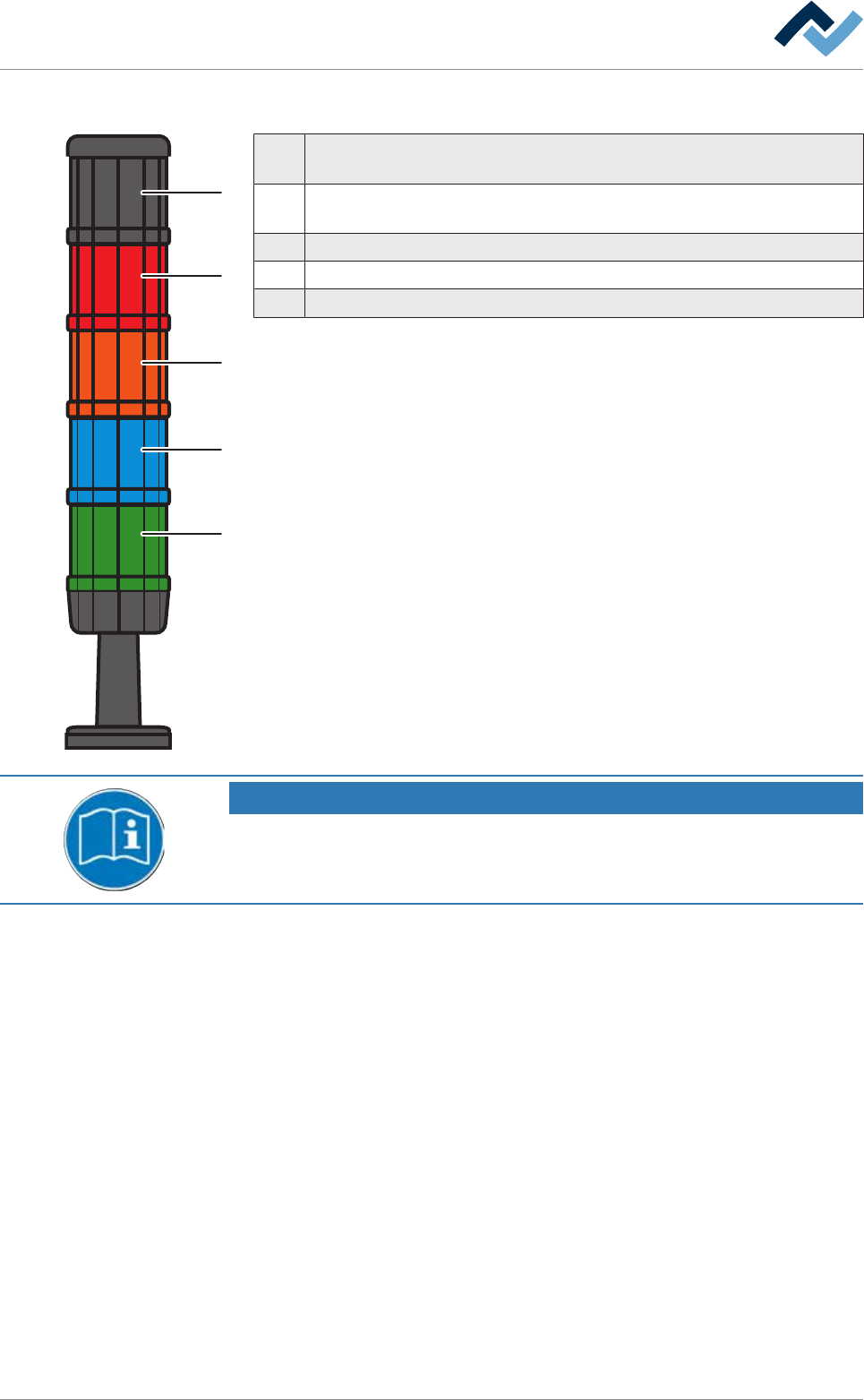
1 Horn: The horn sounds when a message appears for a set period of time.
This function can be disabled.
2 Red: Emergency; dangerous condition, abnormal condition, imminent crit-
ical condition.
3 Orange: Abnormal condition; imminent critical condition.
4 Blue: Mandatory; operator intervention required.
5 Green: Normal condition; wait.
NOTE
Supplementary documents
With respect to this, please also read the document [120062] on the data carrier
[product_data_selective], which is included in the delivery.
Ersa GmbH Operating Instructions_VF335_en|Rev. 14|30/11/2017 124/695
6|Function description
6.3 Prevailing term definitions in this instruction manual
6.3.1 Dialogs
Dialogs are windows in which you can perform settings or read values. They always
fill the entire screen. They can be divided into:
– Start dialog
– Input dialogs
– Setting dialogs
6.3.2 Frames
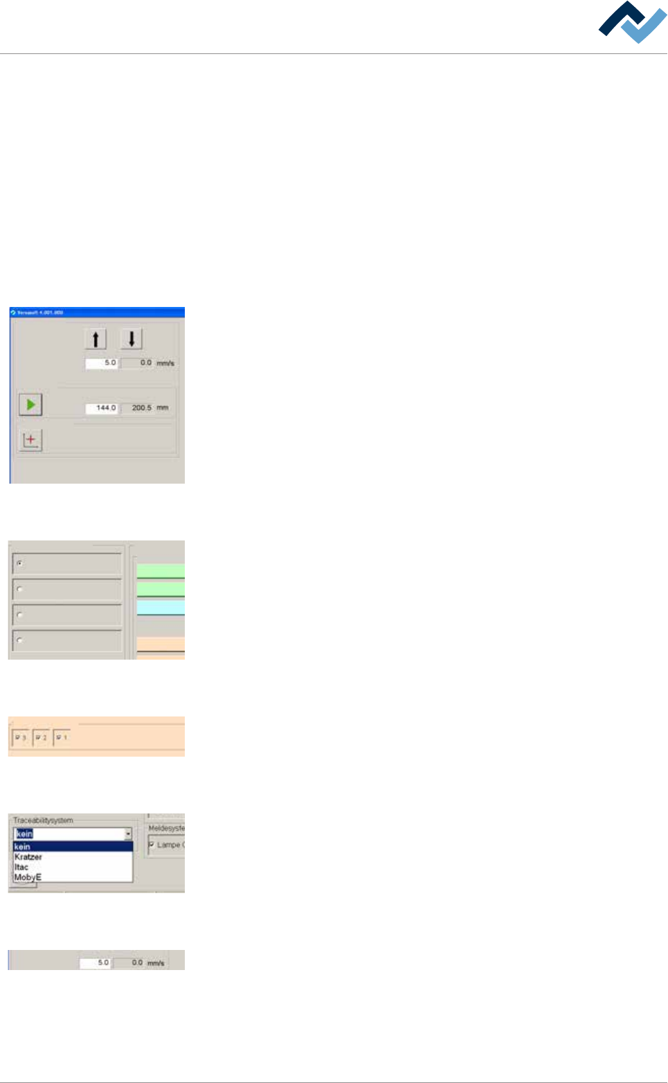
Conveyor width adjustment
Positioning
Set value Actual value
Set value Actual value
Step mode
Special positions
v
Frames are always visibile inside the dialogs. They summarize elements connected
together in a group. The example shown, the input and display fields as well as the
buttons for width adjustment are summarized in a frame.
6.3.3 Radio button
Profile
User administration
Logging
File path
General settings
Settings
User maintenance mode
Preheating
Soldering module
Exit
Default
11
1
Radio buttons are circular and always appear in groups. They can be enabled but
exclude each other. They can only be enabled individually.
6.3.4 Checkbox
Edit dialog Preheating
Heating
power value
Temperature
Sections
user: none maintenance mode
manual
power valuecurrent
Set value Actual value
A checkbox can be enabled by clicking on it. If the checkbox is enabled, a check-
mark appears. As a result, the associated function is enabled.
6.3.5 Dropdown menu
A dropdown menu contains several entries each of which can be individually selec-
ted by clicking on the small triangle on the right. The selected entry is always dis-
played in blue.
6.3.6 Input fields and display fields
Conveyor width adjustment
Positioning
Set value Actual value
Set value Actual value
Step mode
Special positions
v
Input fields always have a white background. Usually, a numerical table for entering
values opens up when these fields are clicked on.
Display fields are always displayed in colour or have a grey background. You cannot
change but only read the assigned values.
Ersa GmbH Operating Instructions_VF335_en|Rev. 14|30/11/2017 125/695