Operating Instructions_VF335_en.pdf - 第433页
8|Service and maintenance b) Lift the replacement rack with the lifting cart until the height (2) between the floor and the lower edge of the replacement rack guide rail is at least 15 mm greater than the height (1) be…
8|Service and maintenance
8.11.9.6 Inserting the (optionally pre-heated) DIP solder pot into the machine
NOTE
Heating up the solder before replacing the DIP solder pot
The solder can be heated up in the optional heating station before replacing the DIP
solder pot. Here it remains solid, but becomes hot. A safety switch in the heating sta-
tion prevents the solder from heating and liquefying any further.
NOTE
To move the DIP solder pot out of the service position, acknowledge the service
message
To be able to move the DIP solder pot out of the service position, acknowledge the
corresponding service message. Afterwards, you will have five minutes to move the
DIP solder pot out of the service position. During this time, a corresponding notice will
be displayed. If the DIP solder pot has not been moved after this time, a timeout mes-
sage appears. After acknowledging the timeout message, you will have another five
minutes to move the DIP solder pot out of the service position.
ü To insert the (optionally pre-heated) DIP solder pot into the machine:
ü You have donned the required protective clothing.
ü The optional heating station is separated from the DIP solder pot.
ü The bar spacer and the height of the replacement rack have been adjusted ac-
cording to the machine configuration.
ü The traction aid is mounted on the machine.
ü The doors and hoods in the area of the soldering module are open.
ü The cover of the gassing hood is open.
a) Lift the replacement rack with the DIP solder pot using the lifting cart.
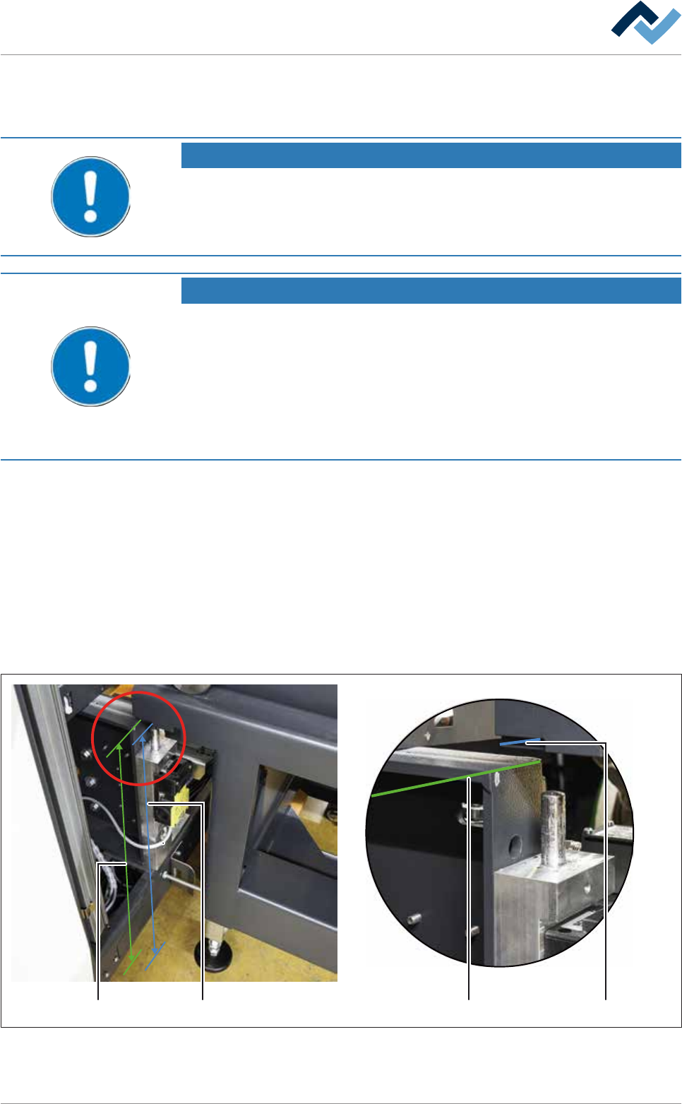
211
2
Fig.169: Determine the height of the replacement rack.
Ersa GmbH Operating Instructions_VF335_en|Rev. 14|30/11/2017 432/695
8|Service and maintenance
b) Lift the replacement rack with the lifting cart until the height (2) between the
floor and the lower edge of the replacement rack guide rail is at least 15 mm
greater than the height (1) between the floor and the DIP soldering module
guide rail.
c) Carefully bring the lifting cart to the machine.
65
2
5 7
Fig.170: Centring the replacement rack using the traction aid
d) Position the replacement rack in such a way that the forklift forks (5) of the lift-
ing cart slide along the traction aid (6) both on the right and on the left.
ð The second worker should give you instructions on how to position the re-
placement rack, since the traction aid is barely visible from the position of
the lifting cart driver.
e) Push the replacement rack towards the machine until the bar spacer hits the
machine frame.
ð The second worker should visually check whether the replacement rack
has been brought completely to the machine.
f) Turn the bar of the lifting cart by 90° (7), so that it cannot roll away.
Ersa GmbH Operating Instructions_VF335_en|Rev. 14|30/11/2017 433/695
8|Service and maintenance
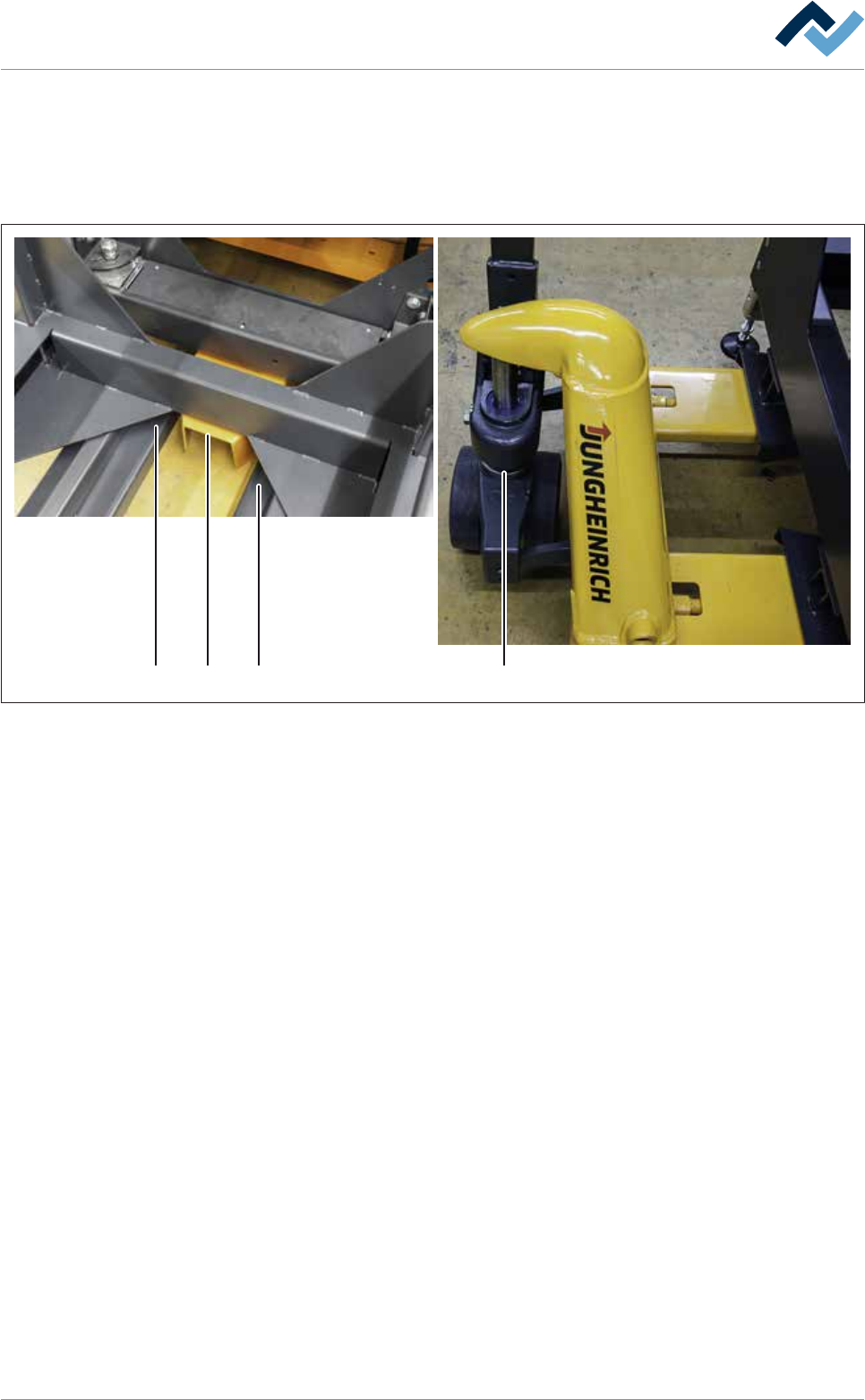
10 9
10 1112 13
Fig.171: Lowering the replacement rack and inserting the switching cams
g) Using the lifting cart, carefully lower the replacement rack until its guide rails
are placed level on both locating surfaces of the machine (11).
ð At this point, the adjustable feet (12) of the replacement rack must be on
the floor.
ð While the equipment is lowered, the switching cams (10) must slide into
the switch and must not be canted.
Ersa GmbH Operating Instructions_VF335_en|Rev. 14|30/11/2017 434/695