Operating Instructions_VF335_en.pdf - 第241页
6|Function description ü To enter the offset value of the width adjustment: a) After referencing, measure the actual distance between the conveyor rails and compare it with the displayed [Actual value] b) If difference…
6|Function description
6.14.8 The settings dialog [Width adjustment]
În this dialog you can set the width adjustment.
NOTE
Are any changes possible?
To access this dialog, the [Module properties] and [Set value pages] user rights are re-
quired. The settings can only be displayed, without user name and password. In this
case, while the password prompt appears, press the [ESC] key on your keyboard or
click on the [Cancel] button.
ü To open the [Conveyor width adjustment] input dialog:
a) In the [Conveyor width adjustment] frame, click on the
button.
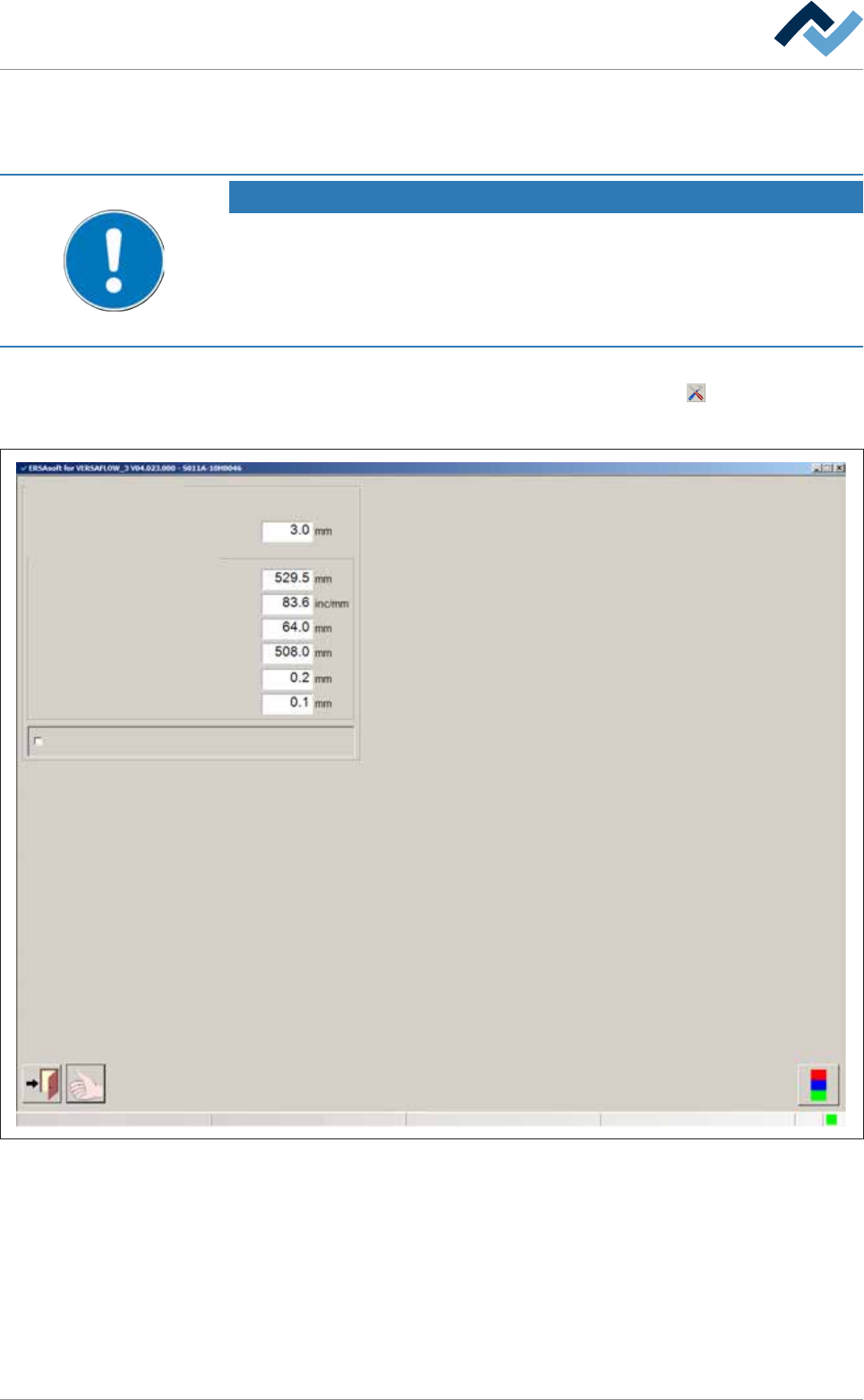
ð The [Conveyor width adjustment] input dialog is displayed:
Conveyor width adjustment
User ersa
Position measuring and ranges
Conveying edge
Offset
Gradient
Position min.
Position max.
Min. difference for positioning
Position window
Enable only step mode
Maintenance mode
Fig.60: The settings dialog [Width adjustment].
ü To set the [Conveying edge]:
a) Enter the width of the conveyor supports (length of chain pins) in [mm] into
the input field.
ð The travel range of the soldering units is limited by this value in order to pre-
vent a collision between the solder nozzle and the conveyor chains. The dia-
meter of the solder nozzle is therefore taken into account. If a conveyor chain
is used with longer chain pins, you need to adjust this value.
Ersa GmbH Operating Instructions_VF335_en|Rev. 14|30/11/2017 240/695

6|Function description
ü To enter the offset value of the width adjustment:
a) After referencing, measure the actual distance between the conveyor rails and
compare it with the displayed [Actual value]
b) If differences result, enter the actual distance into the [Offset] input field.
c) Perform referencing again.
ð The difference will now be taken into account.
ü To change the slope of the characteristic curve:
a) This input field is used for service and diagnostic purposes.
ð It influences the actual value display (slope of the characteristic curve) in the
input dialog [Conveyor width adjustment]
ü To set the minimum/maximum conveyor width:
a) Enter the minimum and the maximum conveyor width into the [Position min.] /
[Position max.] input field.
Ersa GmbH Operating Instructions_VF335_en|Rev. 14|30/11/2017 241/695
6|Function description
6.14.9 Operation of the modules, module maintenance
The fluxing and soldering modules can be enabled via the Module maintenance
user interface. This is necessary if, for example, maintenance or cleaning activities
must be carried out.
Module maintenance can be enabled from the input dialog of the respective mod-
ule if the machine is in the [Maintenance mode] or [Automatic mode] operation
mode.
If in the meantime the selected module is operating, production is completed be-
fore module maintenance is enabled. During this time the [Module maintenance]
button flashes yellow.
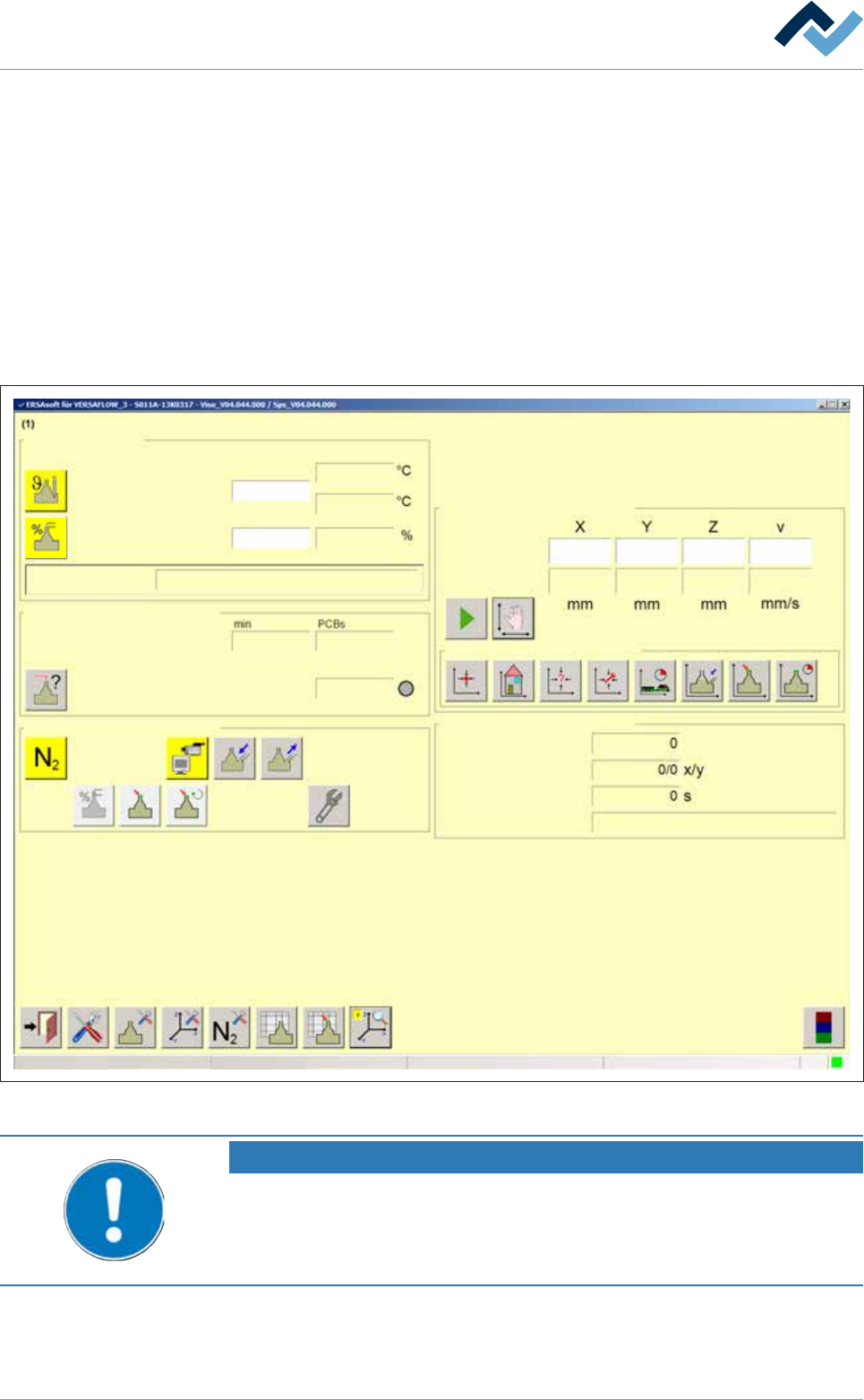
Module maintenance is enabled from the input dialog of the relevant module:
Edit dialog Soldering unit 1 Solder pot 1
Solder pot
user:
none
Maintenance mode
Temperature
Operation mode
Set value Actual value
manual
Module tests
Next test
Wave offset
Switch functions
Manual movement
Set value
Actual value
Automatic positioning
Set no.
Panel
Remaining time
Active tool
Solder
pot 1
Wave power
85
85
295
295
295
007 -
10
3
14616
330.0 -137.0 57.0 100.0
329.8 -136.9 57.1 0.0
Special positions
Fig.61: The [Soldering unit 1 Solder pot 1] input dialog
NOTE
Different description
This document describes all the functions - even those which may not be supported
by your machine equipment. For this reason, the representation of the machine in
your visualization may be different from the functional description at hand.
Ersa GmbH Operating Instructions_VF335_en|Rev. 14|30/11/2017 242/695